SIPLACE-SX4-DX4-用户手册.pdf - 第276页
Description of the circuit boards Gantry 6.2.2 Head Interface C700X-L/R 276 Service Manual SIPLACE SX4/DX4 6.2.2 6 . 2 . 2 H e a d I n t e r f a c e C 7 0 0 X - L / R Head Interface C700X-L/R Head interface [03055067-xx]…
Description of the circuit boards
6.2.1 Vision hotlink adapter [03050555-xx] Gantry
Service Manual SIPLACE SX4/DX4 275
6.2
6.2 Gantry
Gantry
6.2.1
6.2.1 Vision hotlink adapter [03050555-xx]
Vision hotlink adapter [03050555-xx]
03050555-01
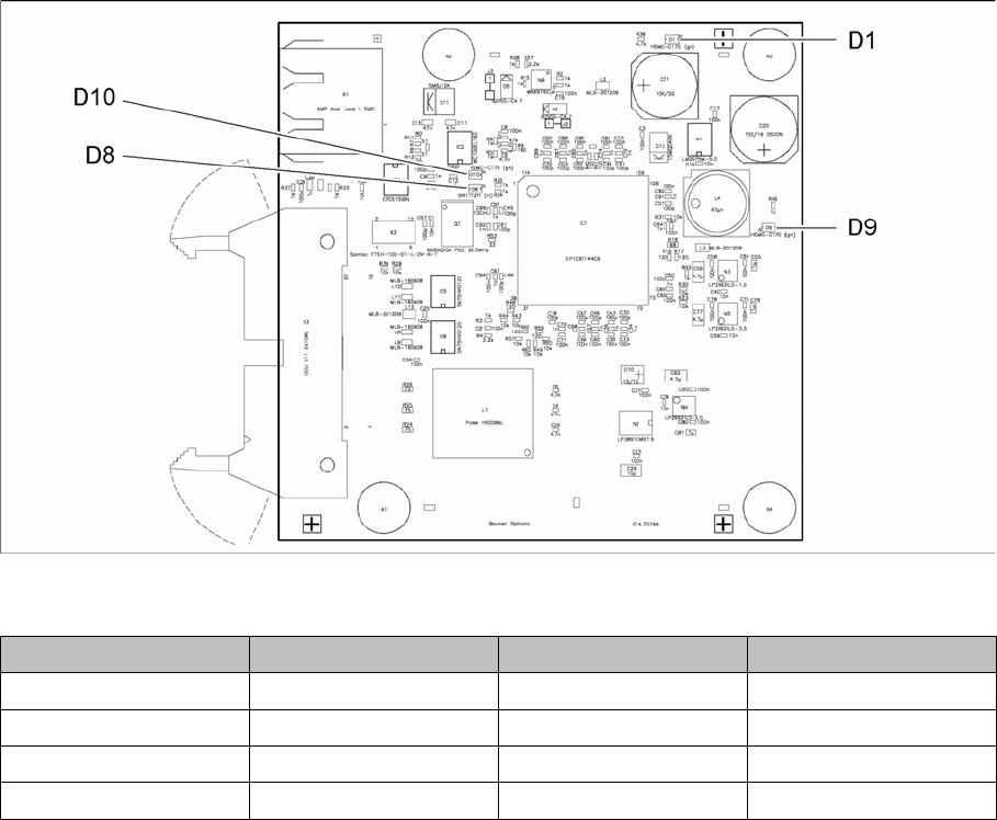
LED [03050555-01]
LED Color Status Description
D1 GN ON +12VDC
D8 RD ON CLKUSR error
D9 GN ON +5 VDC
D10 GN OFF CRC_ERR
Description of the circuit boards
Gantry 6.2.2 Head Interface C700X-L/R
276 Service Manual SIPLACE SX4/DX4
6.2.2
6.2.2 Head Interface C700X-L/R
Head Interface C700X-L/R
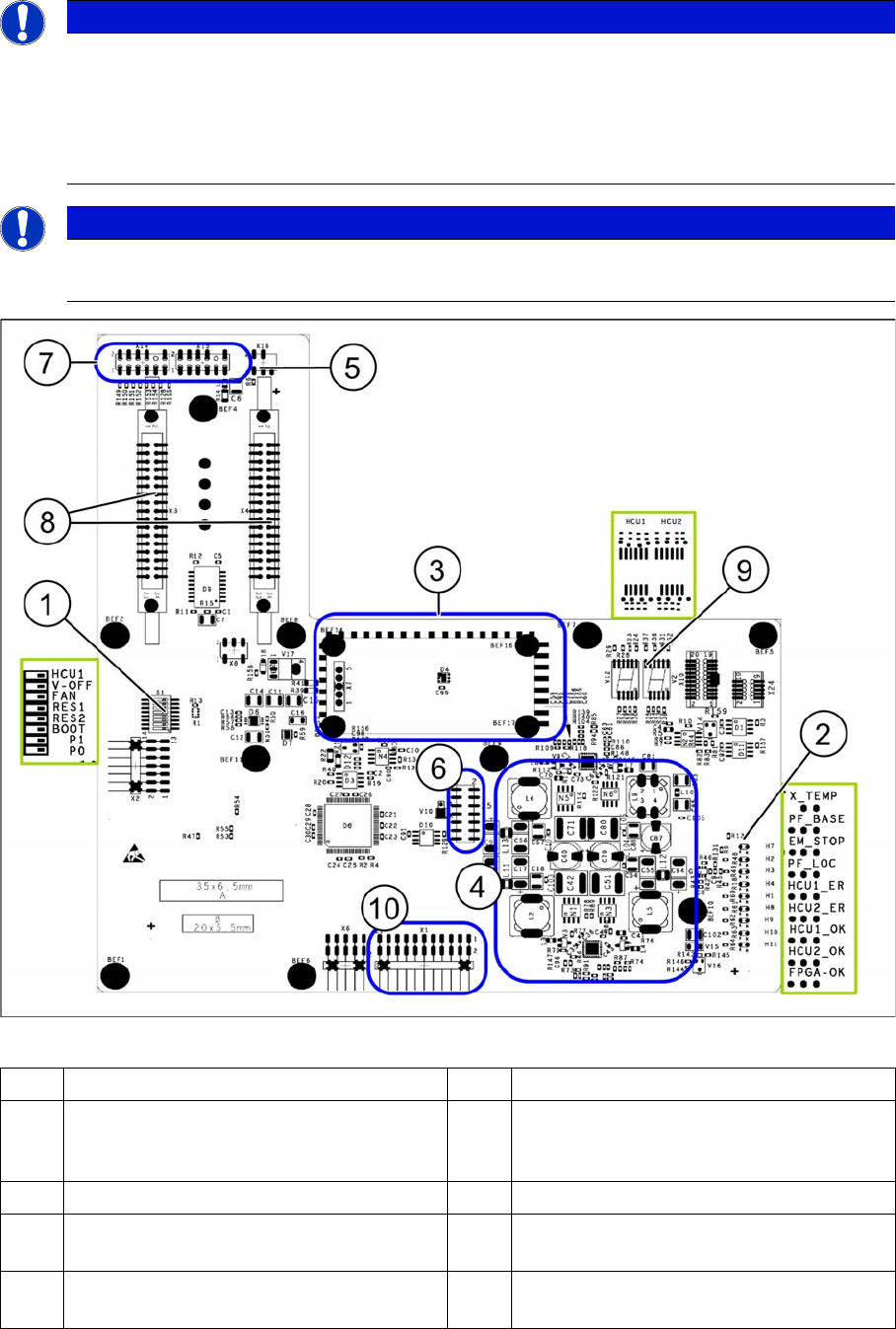
Head interface [03055067-xx] (gantry 1 and 3)
NOTICE
2 versions
The head interface version used will depend on the gantry. The elements on these two boards
are arranged in a mirrored order. However, the function is the same.
► MODULE/head interface C700X-L [03055068Sxx] for gantry 1 and 3
► MODULE/head interface C700X-R [03055070Sxx] for gantry 2 and 4
NOTICE
C&P20 P
If you are converting to an C&P20 P, the head interface must have at least function state -05.
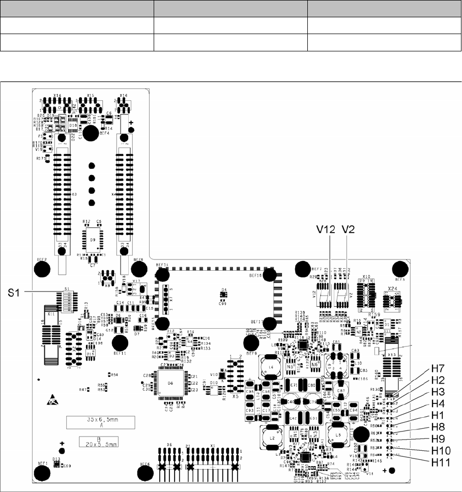
1 DIP switch block S1. 2 LED H2- H11
3 Power cube X7 24V (input 42V) 4 DC/DC converter +15 V, -15 V, +5 V,
+3.3 V, +1.5 V (input 24 V from power
cube)
5 X16 From temperature sensor X motor 6 X5 From vision board (CAN_H/L)
7 X14, X15 (see below) 8 X3-X4 Flat ribbon cables from gantry inter-
face
9 7-segment display HCU 1(V12) and HCU2
(TWIN segment 2 – V2)
10 X1 service connector
Description of the circuit boards
6.2.2 Head Interface C700X-L/R Gantry
Service Manual SIPLACE SX4/DX4 277
Connector assignment X14, X15
6.2.2.1
6.2.2.1 Head interface C700X-L [03055068-xx]
Head interface C700X-L [03055068-xx]
03055067-05
Connector Up to version -02 From version -03
X14 Old incremental encoder New incremental encoder
X15 Test connector for track signals Old incremental encoder