SIPLACE-SX4-DX4-用户手册.pdf - 第278页
Description of the circuit boards Gantry 6.2.2 Head Interface C700X-L/R 278 Service Manual SIPLACE SX4/DX4 LED [03055067-05] 7-segment disp lay V2 [03055067-05] 7-segment display V1 2 [03055067-05] Dip switch S1 [0305506…
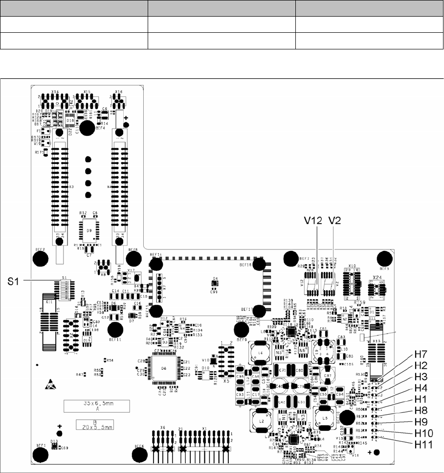
Description of the circuit boards
6.2.2 Head Interface C700X-L/R Gantry
Service Manual SIPLACE SX4/DX4 277
Connector assignment X14, X15
6.2.2.1
6.2.2.1 Head interface C700X-L [03055068-xx]
Head interface C700X-L [03055068-xx]
03055067-05
Connector Up to version -02 From version -03
X14 Old incremental encoder New incremental encoder
X15 Test connector for track signals Old incremental encoder
Description of the circuit boards
Gantry 6.2.2 Head Interface C700X-L/R
278 Service Manual SIPLACE SX4/DX4
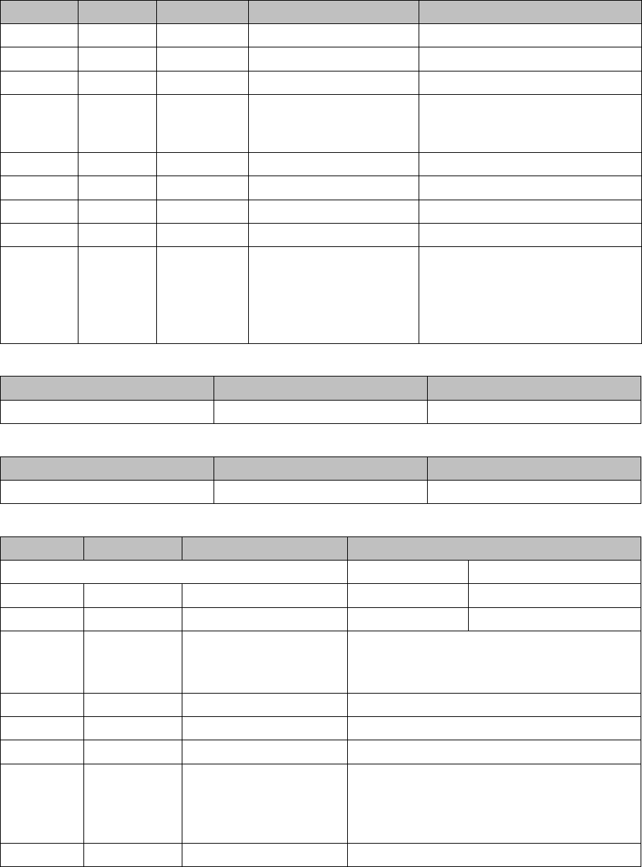
LED [03055067-05]
7-segment display V2 [03055067-05]
7-segment display V12 [03055067-05]
Dip switch S1 [03055067-05]
LED Color Status Signal name Description
H1 RD - HCU1_LED_ERROR Not used
H2 RD ON POWERFAIL_BASE PowerFail from power supply
H3 RD ON EMERGENCY-STOP_3V Emergency stop or cover opened
H4 RD ON POWERFAIL_LOCAL_3V Power fail local: monitors voltages
generated by DC/DC converter
+15V, -15V, +5V, +3.3V, +1.5V
H7 RD ON X_TEMP_SENS X motor: temperature too high
H8 RD - HCU2_LED_ERROR Not used
H9 RD - HCU1_LED_READY Not used
H10 RD - HCU2_LED_READY Not used
H11 GN ON LED_5V_OK FPGA OK
Field Programmable Gate Array –
Monitors the microcontroller on the
basic adapter board. This LED
should always be green.
Display Status Description
Decimal point Flashes HCU2 OK
Display Status Description
Decimal point Flashes HCU1 OK
Switch Status Signal name Description
Gantry 1 Gantry 3
S1.1 OFF/ON Gantry_ID0 OFF OFF
S1.2 OFF/ON Gantry_ID1 OFF ON
S1.3 OFF COM_BOOT_HCU ON: set HCU to bootstrap mode
RES1 to ON. BOOT to ON. RES1 OFF. BIOS
download via external interface possible.
S1.4 OFF RESET_HCU2 ON: Reset HCU2
S1.5 OFF RESET_HCU1 ON: Reset HCU1
S1.6 OFF FAN Not used
S1.7 OFF DCDC_OFF DC/DC converter
Standard OFF. A reset (ON) is possible if not
all voltages are present (power fail LEDs on
the basic adapter board)
S1.8 OFF HCU_1_2 Not used
Description of the circuit boards
6.2.2 Head Interface C700X-L/R Gantry
Service Manual SIPLACE SX4/DX4 279
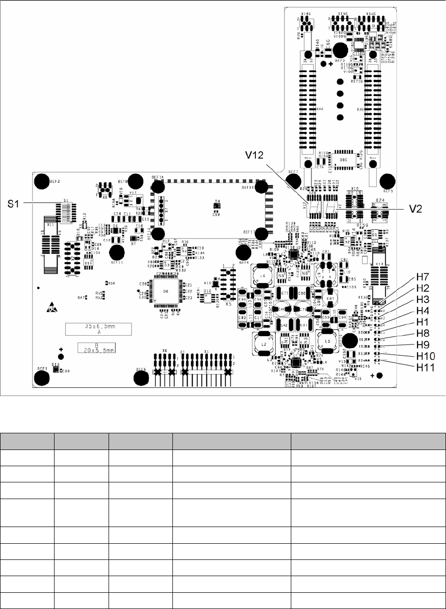
6.2.2.2
6.2.2.2 Head interface C700X-R [03055070-xx]
Head interface C700X-R [03055070-xx]
03055069-05
LED [03055069-05]
LED Color Status Signal name Description
H1 RD - HCU1_LED_ERROR Not used
H2 RD ON POWERFAIL_BASE PowerFail from power supply
H3 RD ON EMERGENCY-STOP_3V Emergency stop: hood opened
H4 RD ON POWERFAIL_LOCAL_3V PowerFail local: errors at 1.5V,
3.3V, 5V, +15V, -15V
H7 RD ON X_TEMP_SENS X motor: temperature too high
H8 RD - HCU2_LED_ERROR Not used
H9 RD - HCU1_LED_READY Not used
H10 RD - HCU2_LED_READY Not used
H11 GN ON LED_5V_OK FPGA OK