SIPLACE-SX4-DX4-用户手册.pdf - 第282页
Description of the circuit boards Gantry 6.2.4 X base adapter C&P [03045647-xx] 282 Service Manual SIPLACE SX4/DX4 6.2.4 6 . 2 . 4 X b a s e a d a p t e r C & P [ 0 3 0 4 5 6 4 7 - x x ] X base adapter C&P [0…
Description of the circuit boards
6.2.3 Vision board spread spectrum HCU [03067289-xx] Gantry
Service Manual SIPLACE SX4/DX4 281
LED [03067289-02]
Dip switch S1 [03067289-02]
6.2.3.1
6.2.3.1 DIP Switch on the Vision Board (Digital Version 02)
DIP Switch on the Vision Board (Digital Version 02)
* Not all gantries may be available, depending on the machine type.
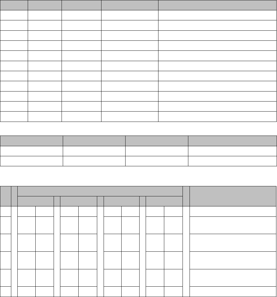
LED Color Status Signal name Description
D9 GN ON LED_XC_OK RUN
D10 RD ON LED_XC_ERR ERROR
D12 RD ON XC_RESET RESET
D13 GN ON IO/LVDS51P PCB camera active
D14 GN ON IO/LVDS51N CO camera active
D16 GN ON P12VCAM_I +12VDC for camera
D18 GN ON P5VCAM +5VDC for camera
D19 GN ON P2.5VCAM + 2.5 VDC for camera
D20 GN ON P3.3VCAM + 3.3VDC for camera
D23 GN ON P5V +5VDC
D25 GN ON P15V +15VDC
Switch Status Signal name Description
S1.1 OFF HW_RESET ON: RESET CAN controller
S1.2 OFF CAN_ID Not used
S Gantry* Comments
1 2 3 4
1 OFF OFF OFF OFF Reset - CAN processor
2 OFF ON OFF ON PID0 address switch 1 -> gan-
try
3OFF OFF ON ONPID1 address switch 2 -> gan-
try
4 OFF OFF OFF OFF CAN R - switch for the terminal
resistor on the CAN bus
5ON ON ON ONSpeed: ON = 1 Mbit/s, OFF =
500 Kbit/s
6ON ON ON ONCAN ID - for X machine ON
Description of the circuit boards
Gantry 6.2.4 X base adapter C&P [03045647-xx]
282 Service Manual SIPLACE SX4/DX4
6.2.4
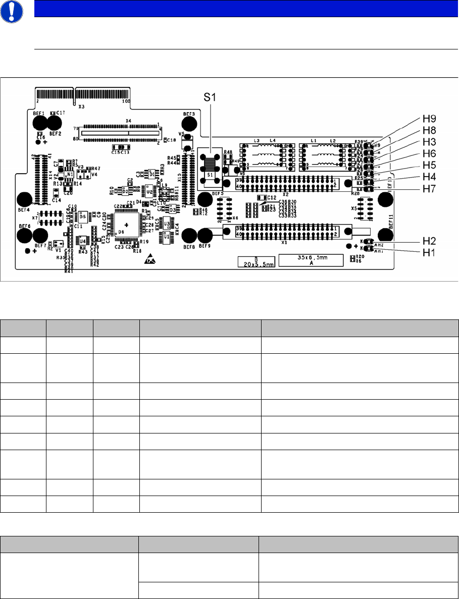
6.2.4 X base adapter C&P [03045647-xx]
X base adapter C&P [03045647-xx]
This board is used for C&P20x and CPP heads on X series S and SX4/DX4 machines.
Version 05
03045647-05
LED [03045647-05]
Switch S1 [03045647-05]
Switch S1 sets the link voltage for the Z axis
If the setting is incorrect, no damage will be done but an HCU error message will be issued.
NOTICE
C&P20 P
The X basis adapter needs at least function state 08 for the C&P20 P head.
LED Color Status Signal name Description
H1 GN ON CO_SENSOR CO sensor active
H2 GN ON - The programming plug for the HCU is con-
nected
H3 RD ON FPGA_TEST_6 1.5V power supply error
H4 RD ON FPGA_TEST_2 3.3V power supply error
H5 RD ON FPGA_TEST_4 5V power supply error
H6 RD ON FPGA_TEST_1 15V power supply error
H7 RD ON FPGA_TEST_3 DP power supply error, temp. without func-
tion
H8 RD ON FPGA_TEST_5 24V power supply error
H9 RD ON POWERFAIL_LOCAL PowerFail on circuit board
Switch Status Function
S1 40V Intermediate link voltage for Z axis -->
C&P20
150V Intermediate link voltage for Z axis --> CPP
Description of the circuit boards
6.2.4 X base adapter C&P [03045647-xx] Gantry
Service Manual SIPLACE SX4/DX4 283
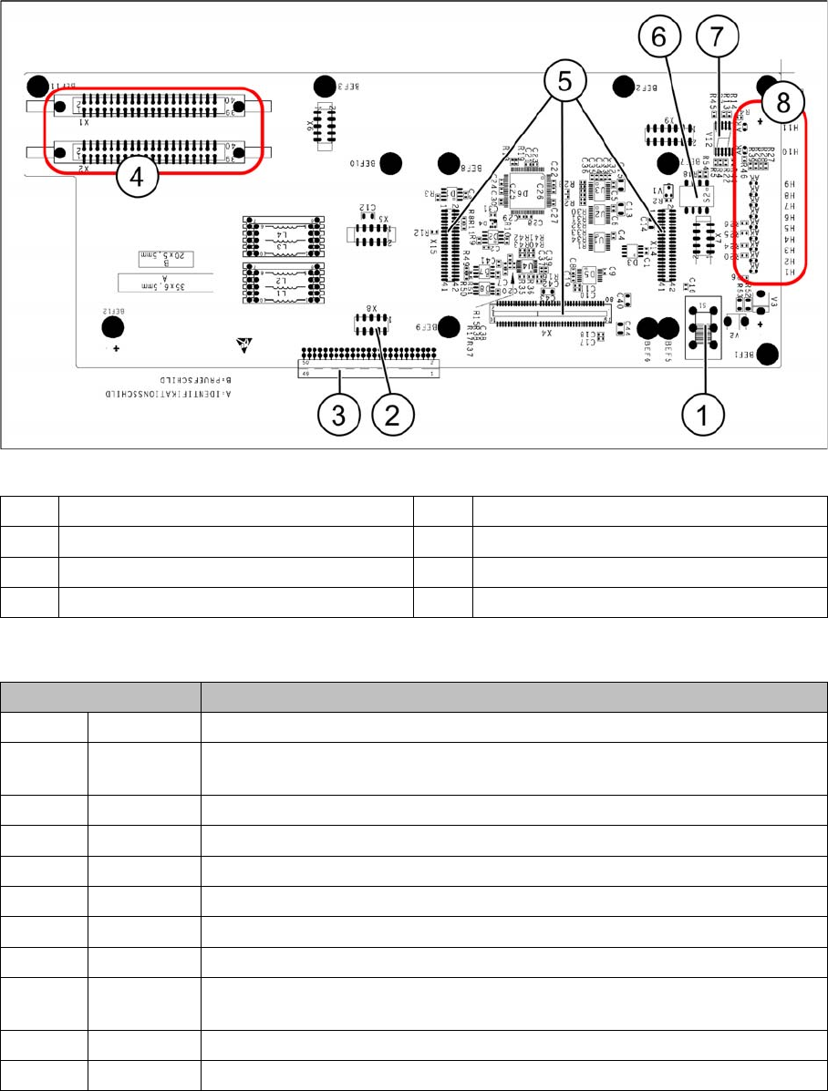
Before version 05
Base adapter board (without HCU)
LEDs - meanings
The voltage monitors trigger as soon as the nominal voltage is undershot by 5%.
1 Switch S1 (see above) 2 X4 – for checking the voltages
3 Connection to the head interface C700 4 X1 and X2 – to the head
5 X4, X14 and X15 – for the HCU 6 DIP switch S2
7 7 segment display. 8 LEDs H1-H11
LED Description
H1 BE-S Lights up green, when the CO sensor is actuated
H2 RS232 Lights up, when the programming connector for the HCU is connected (not
designed for Service)
H3 1V5 1.5 voltage monitor - lights up red in case of an error
H4 3V3 3.3 voltage monitoring - lights up red in case of an error
H5 5V 5 voltage monitor - lights up red in case of an error
H6 15V 15 voltage monitoring - lights up red in case of an error
H7 DP DP voltage monitoring (currently without function)
H8 24V 24 V voltage monitoring - lights up red in case of an error
H9 LOC Voltage monitor local - lights up red as soon as one of the voltage monitors
triggers.
H10 Ok HCU-OK - HCU running without errors
H11 ERR HCU error - HCU reports an error