SIPLACE-SX4-DX4-用户手册.pdf - 第284页
Description of the circuit boards Gantry 6.2.4 X base adapter C&P [03045647-xx] 284 Service Manual SIPLACE SX4/DX4 Switch S2 All switches must be set to OFF . If needed, the HCU can be reset with S3. Further Informat…
Description of the circuit boards
6.2.4 X base adapter C&P [03045647-xx] Gantry
Service Manual SIPLACE SX4/DX4 283
Before version 05
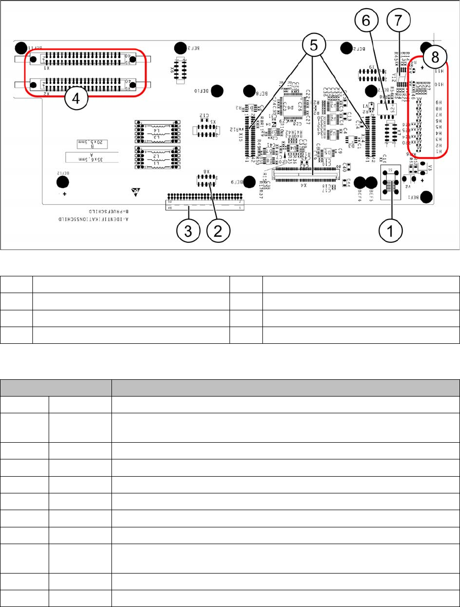
Base adapter board (without HCU)
LEDs - meanings
The voltage monitors trigger as soon as the nominal voltage is undershot by 5%.
1 Switch S1 (see above) 2 X4 – for checking the voltages
3 Connection to the head interface C700 4 X1 and X2 – to the head
5 X4, X14 and X15 – for the HCU 6 DIP switch S2
7 7 segment display. 8 LEDs H1-H11
LED Description
H1 BE-S Lights up green, when the CO sensor is actuated
H2 RS232 Lights up, when the programming connector for the HCU is connected (not
designed for Service)
H3 1V5 1.5 voltage monitor - lights up red in case of an error
H4 3V3 3.3 voltage monitoring - lights up red in case of an error
H5 5V 5 voltage monitor - lights up red in case of an error
H6 15V 15 voltage monitoring - lights up red in case of an error
H7 DP DP voltage monitoring (currently without function)
H8 24V 24 V voltage monitoring - lights up red in case of an error
H9 LOC Voltage monitor local - lights up red as soon as one of the voltage monitors
triggers.
H10 Ok HCU-OK - HCU running without errors
H11 ERR HCU error - HCU reports an error
Description of the circuit boards
Gantry 6.2.4 X base adapter C&P [03045647-xx]
284 Service Manual SIPLACE SX4/DX4
Switch S2
All switches must be set to OFF. If needed, the HCU can be reset with S3.
Further Information
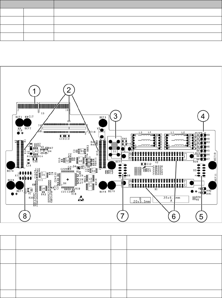
Base adapter for CPx [03045647-xx] on machines with HCU
Switch Description
S1 S0 Gantry encoding (currently not used)
S2 S1 Gantry encoding (currently not used)
S3 Reset Reset HCU
S4 Boot HCU bootstrap function activated (not designed for Service)
1 X3 Connection to the head interface board
C700
5 Test connector for FPGA
2 X4, X14, X15 – connector for HCU 6 X1-X2 flat ribbon connection for CPP or
C&P20
3 Switch S1 intermediate circuit voltage
Z axis
40V C&P20 (switch top)
150V CPP(switch bottom)
7 X6 Programming connector for FPGA
4 LED H3- H9 8 X7 Test connector HCU

Description of the circuit boards
6.2.4 X base adapter C&P [03045647-xx] Gantry
Service Manual SIPLACE SX4/DX4 285
Meaning of LEDs H1 - H9
The voltage monitors trigger as soon as the target voltage is exceeded or undershot by 5%.
H1 Ok Status display for the component sensor
H2 RS232 Shines when the programming connector for the HCU1 is connected (not de-
signed for Service)
H3 1V5 Voltage monitor 1.5 V, shines red in event of errors
H4 3V3 Voltage monitor 3.3 V, shines red in event of errors
H5 5V Voltage monitor 5 V, shines red in event of errors
H6 15V Voltage monitor 15 V, shines red in event of errors
H7 DP Voltage monitor DP (currently without function)
H8 24V Voltage monitor 24 V, shines red in event of errors
H9 LOC Voltage monitor local - shines red as soon as one of the voltage monitors trig-
gers (not for 24 V)