SIPLACE-SX4-DX4-用户手册.pdf - 第288页
Description of the circuit boards Gantry 6.2.5 X base adapter TWIN [03054879-xx] 288 Service Manual SIPLACE SX4/DX4 Switch S1 All switches must be set to OFF . If required, the HCU can be r eset with the "reset"…
Description of the circuit boards
6.2.5 X base adapter TWIN [03054879-xx] Gantry
Service Manual SIPLACE SX4/DX4 287
Older versions:
Base adapter board (without HCU)
LEDs - meanings
The voltage monitors trigger as soon as the nominal voltage is undershot by 5%.
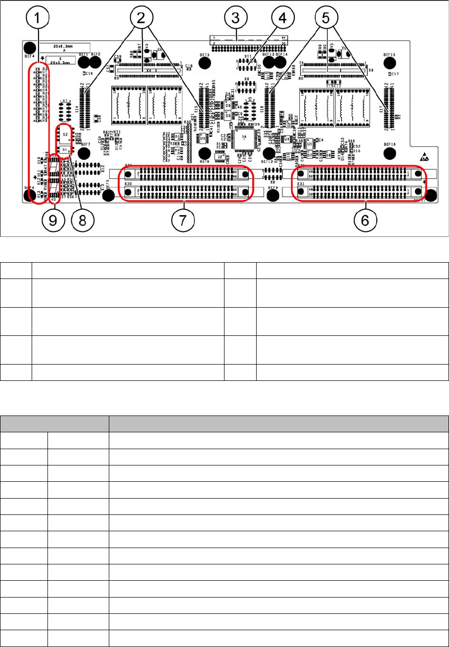
1 LEDs H1-H13 2 X4, X14, X15 – connector for HCU1
3 X3 – connector to the gantry interface
board C700
4 X11 – service connector for checking the
voltages
5 X9, X16, X17 – connector for HCU2 6 X32, X33 – connector for segment 2 flat rib-
bon cable
7 X30, X31 – connector for segment 1 flat rib-
bon cable
8 DIP switches S1 and S2
9 7-segment displays
LED Description
H1 RS232 Lights up when the HCU1 programming connector is plugged in
H2 RS232 Lights up, when the HCU2 programming connector is plugged in
H3 1V5 1.5 V voltage monitoring - lights up red in case of an error
H4 3V3 3.3 V voltage monitoring - lights up red in case of an error
H5 5V 5 V voltage monitoring - lights up red in case of an error
H6 15V 15 V voltage monitoring - lights up red in case of an error
H7 DP DP voltage monitoring – (currently without function)
H8 24V 24 V voltage monitoring - lights up red in case of an error
H9 LOC Voltage monitoring local - lights up as soon as the voltage monitors triggers.
H10 Ok HCU1-OK - HCU running without errors
H11 ERR HCU1 error - HCU reports an error
H12 Ok HCU2-OK - HCU running without errors
H13 ERR HCU2 error - HCU reports an error

Description of the circuit boards
Gantry 6.2.5 X base adapter TWIN [03054879-xx]
288 Service Manual SIPLACE SX4/DX4
Switch S1
All switches must be set to OFF. If required, the HCU can be reset with the "reset" button.
Switch S2
All switches must be set to OFF. If required, the HCU can be reset with the "reset" button.
Switch Description
S1 Not used No function
S2 Reset HCU
2
Resets the HCU2
Switch Description
S1 Boot Bootstrap function for the HCUIs
S2 Reset HCU
1
Resets the HCU1
S3 S1 Gantry encoding (currently not used)
S4 S0 Gantry encoding (currently not used)
Description of the circuit boards
6.3.1 Conveyor control TSP410C, control module [03077468-xx] Conveyor
Service Manual SIPLACE SX4/DX4 289
6.3
6.3 Conveyor
Conveyor
6.3.1
6.3.1 Conveyor control TSP410C, control module [03077468-xx]
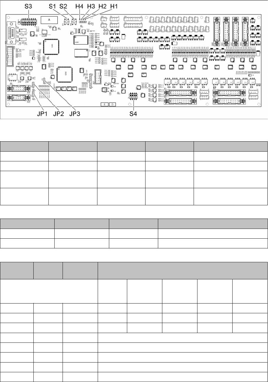
Conveyor control TSP410C, control module [03077468-xx]
03077468-02
LED [03077468-02]
Button S1 and S2 [03077468-02]
Dip switch S3 [03077468-02]
LED Color Status Signal name Description
H1 RD ON LED_FAIL Error
H2 GN ON LED_RUN Running
H3 YE ON LED_CAN1 CAN bus activity to ma-
chine
H4 YE ON LED_CAN2 CAN bus activity
2. conveyor control
Buttons Status Signal name Description
S1 OFF /MR ON: Reset
S2 OFF /BSL ON: boot
Switch Status Signal
name
Description
Single
conveyor
Dual con-
veyor, lane
1
Dual con-
veyor, lane
2
Quad lane
1R/1L
Quad lane
2R/2L
S3.1 ON/OFF /DIP1 OFF OFF ON OFF ON
S3.2 ON/OFF /DIP2 OFF ON OFF ON OFF
S3.3 ON/OFF /DIP3 OFF OFF OFF ON ON
S3.4 OFF /DIP4 Reserved
S3.5 ON /DIP5 Reserved
S3.6 OFF /DIP6 Reserved
S3.7 OFF /EBSL ON: bootstrap mode
S3.8 OFF /EXTSTRT Flash memory internal, ON: flash memory external