SIPLACE-SX4-DX4-用户手册.pdf - 第293页
Description of the circuit boards 6.5.1 Vision LED driver VLT 33 [03039244-xx] Stationary cameras Service Manual SIPLACE SX4/DX4 293 6.5 6 . 5 S t a t io n a r y c a m e r a s Stationary cameras 6.5.1 6 . 5 . 1 V is io n…
Description of the circuit boards
COT insert 6.4.1 Connecting assy FCU [03059783-xx]
292 Service Manual SIPLACE SX4/DX4
6.4
6.4 COT insert
COT insert
6.4.1
6.4.1 Connecting assy FCU [03059783-xx]
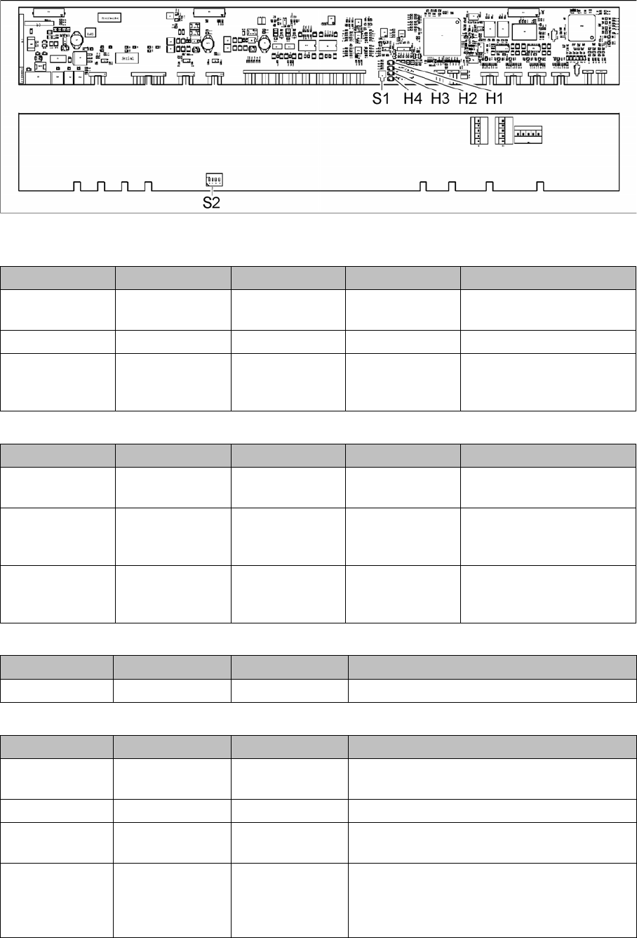
Connecting assy FCU [03059783-xx]
03059783-04
LED (test mode for reject box switched off – S2.1 ON) [03059783-04]
LED (test mode for reject box switched on – S2.1 OFF) [03059783-04]
Button S1 [03059783-04]
Dip switch S2 [03059783-04]
LED Color Status Signal name Description
H1, H2, H3, H4 GN Sequential shift
light
LED1, 2, 3, 4 FCU OK
H1, H2, H3, H4 GN ON LED1, 2, 3, 4 eSW application missing
H1, H2, H3, H4 GN Flashing LED1, 2, 3, 4 FCU error, reboot place-
ment machine or replace
FCU
LED Color Status Signal name Description
H1 or H2 or H3 or
H4
GN Flashes LED1 or 2 or 3 or
4
No sensor connected for
reject box 1 or 2 or 3 or 4
H1 or H2 or H3 or
H4
GN OFF LED1 or 2 or 3 or
4
Sensor for reject boxes 1 or
2 or 3 or 4 connected, but
no reject box inserted
H1 or H2 or H3 or
H4
GN ON LED1 or 2 or 3 or
4
Sensor for reject boxes 1 or
2 or 3 or 4 connected, but
no reject box inserted
Buttons Status Function Description
S1 OFF RESET When pressed
Switch Status Signal name Description
S2.1 ON/OFF FCU_ENV3 ON: test mode for reject box switched off
OFF: test mode for reject box switched on
S2.2 OFF FCU_ENV2 40-fold FCU
S2.3 ON/OFF FCU_ENV1 ON: without insert control, with virtual button
OFF: with insert control, without virtual button
S2.4 ON/OFF FCU_ENV0 ON: with tape cutter and with nozzle changer
functionality
OFF: without tape cutter and without nozzle
changer functionality
Description of the circuit boards
6.5.1 Vision LED driver VLT 33 [03039244-xx] Stationary cameras
Service Manual SIPLACE SX4/DX4 293
6.5
6.5 Stationary cameras
Stationary cameras
6.5.1
6.5.1 Vision LED driver VLT 33 [03039244-xx]
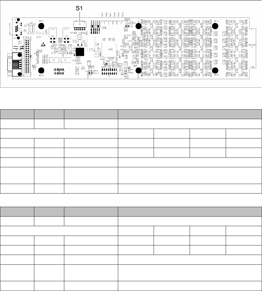
Vision LED driver VLT 33 [03039244-xx]
This board is part of the stationary camera SST25, SST33 and SST36. The stationary cameras which
can be fitted vary according to the machine type used.
03039244-03
DIP switch S1 for SST25 [03039244-03]
DIP switch S1 for SST33, 36 [03039244-03]
Switch Status Signal name Description
S1.1 OFF VCU_CODE OFF: normal operation, ON: Reset
Gantry 1 Gantry 2 Gantry 3 Gantry 4
S1.2 ON/OFF GANTRY_ID_0 OFF ON OFF ON
S1.3 ON/OFF GANTRY_ID_1 OFF OFF ON ON
S1.4 OFF SMD_LED OFF: standard LED, ON: SMD LED
S1.5 OFF CAN_H OFF: with CAN terminator
ON: without CAN terminator
S1.6 OFF CAN_GROUP OFF: FC camera, ON: IC camera
Switch Status Signal name Description
S1.1 OFF VCU_CODE OFF: normal operation, ON: Reset
Gantry 1 Gantry 2 Gantry 3 Gantry 4
S1.2 ON/OFF GANTRY_ID_0 OFF ON OFF ON
S1.3 ON/OFF GANTRY_ID_1 OFF OFF ON ON
S1.4 OFF SMD_LED OFF: standard LED, ON: SMD LED
S1.5 OFF CAN_H OFF: with CAN terminator
ON: without CAN terminator
S1.6 ON CAN_GROUP ON: IC camera , OFF: FC camera
Description of the circuit boards
Nozzle Changers 6.6.1 NC main board CPx [03069324-xx]
294 Service Manual SIPLACE SX4/DX4
6.6
6.6 Nozzle Changers
Nozzle Changers
6.6.1
6.6.1 NC main board CPx [03069324-xx]
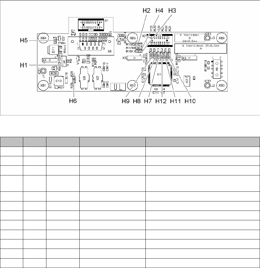
NC main board CPx [03069324-xx]
03069324-02
LED [03069324-02]
LED Color Status Signal name Description
H1 GN ON LED_Magazines_OK Magazines inserted properly
H2 GN ON LED_LB_OPENED Actuator light barrier "open"
H3 GN ON LED_LB_CLOSED Actuator light barrier "closed"
H4 GN ON LED_FPGA_OK FPGA has been loaded and is ready for op-
eration
H5 GN ON SWITCH_VALVE Valve voltage of +24V present
H6 GN ON P3V3 Logic voltage +3.3V present
H7 RD ON FPGA_TEST_6 Internal FPGA status 1
H8 RD ON FPGA_TEST_2 Internal FPGA status 2
H9 RD ON FPGA_TEST_4 Internal FPGA status 3
H10 RD ON FPGA_TEST_1 Internal FPGA status 4
H11 RD ON FPGA_TEST_3 Internal FPGA status 5
H12 RD ON FPGA_TEST_5 Internal FPGA status 6