SIPLACE-SX4-DX4-用户手册.pdf - 第30页
Overview of the Modules Cutter 2.9.4 Width Adjustment 30 Service Manual SIPLACE SX4/DX4 2.13 2 . 1 3 C u t t e r Cutter 2.14 2 . 1 4 D o c k in g S t a t io n f o r X - S e r ie s C o m p o n e n t T r o lle y Docking St…
Overview of the Modules
2.9.4 Width Adjustment X-Series component trolley
Service Manual SIPLACE SX4/DX4 29
2.11
2.11 X-Series component trolley
X-Series component trolley
See also
3.11 X-Series Component Trolley [ ➙ 183]
2.12
2.12 Manual Table for DX4
Manual Table for DX4
See also
3.11 X-Series Component Trolley [ ➙ 183]
1. Guide castor
2. Fixed castor
3. Locking strip
4. Support block
1
4
3
2
1. Upper section
2. Lower section
3. Waste tape container
Overview of the Modules
Cutter 2.9.4 Width Adjustment
30 Service Manual SIPLACE SX4/DX4
2.13
2.13 Cutter
Cutter
2.14
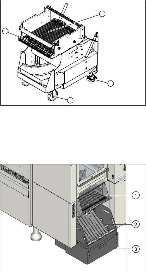
2.14 Docking Station for X-Series Component Trolley
Docking Station for X-Series Component Trolley
1. Pneumatic cylinder
2. Electrical connection
3. Solenoid valves.
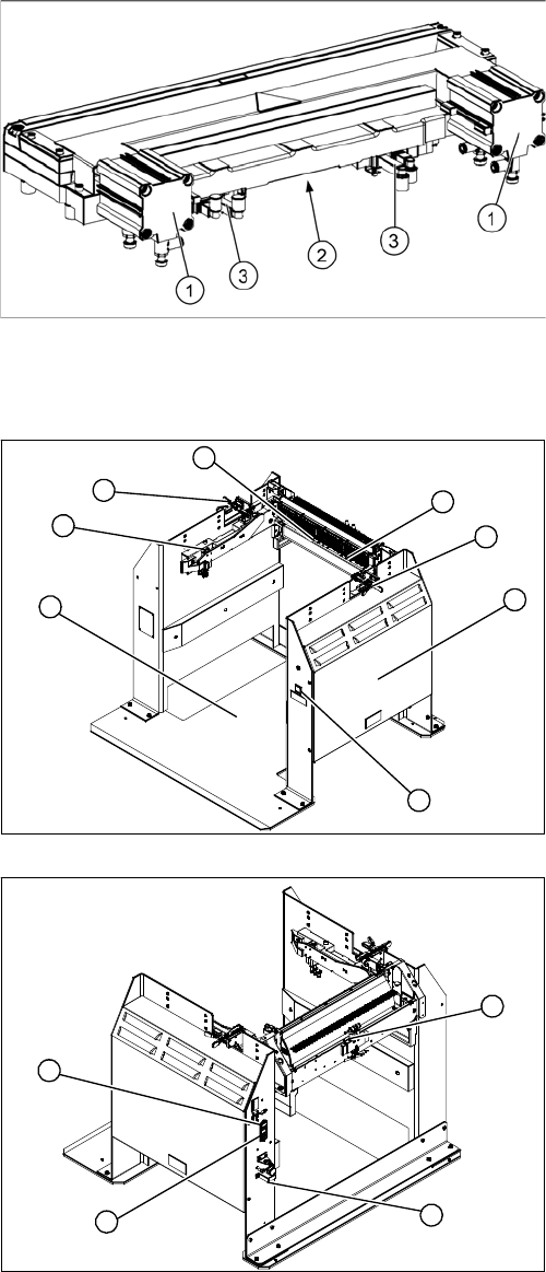
1. Docking station – assembly [00116933-xx]
2. Unlocking pushbutton [00334095-xx]
3. Cover (with power pack behind [03025938-XX] and
pressure control valve for locking cylinder)
4. Locking lever [03025104-xx]
5. Feeder unlock device 40-fold [03011582-XX]
6. Feeder Control Unit (FCU)
Prior to FS04: [03020068-xx]
From FS04: [03066685-xx]
7. Short-stroke cylinder for locking unit [03034831-xx]
1. Control valve [03003489-xx]
2. ON/OFF switch
3. Microfuse [03033387-xx]
4. Pressure control valve for bulkcase feeder and main
connection (5.5 bar)
3
4
1
7
6
5
4
2
1
4
3
2
Service Work
3.1.1 Replacing the Gas Pressure Shock Absorber on the Cover [03086743-xx] Basic Machine
Service Manual SIPLACE SX4/DX4 31
3
3 Service Work
Service Work
3.1
3.1 Basic Machine
Basic Machine
3.1.1
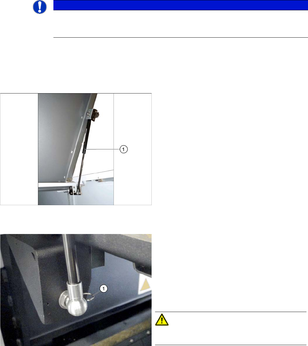
3.1.1 Replacing the Gas Pressure Shock Absorber on the Cover [03086743-xx]
Replacing the Gas Pressure Shock Absorber on the Cover [03086743-xx]
Parts, equipment and tools
▪ Gas pressure spring D3D3B90-135-430-004/230N [03086743-xx]
▪ Loctite 638 [00317731-xx], if required (for loose screwed fixtures)
Overview
Removal
► Release and remove the circlip on the top holder of the gas pressure shock absorber.
► Remove the gas pressure shock absorber from the spherical head on the top and bottom holder.
NOTICE
Loose screwed fixtures
► Also observe section "3.1.1.1 Troubleshooting – Loose Screwed Fixtures on the Gas
Springs" [ ➙ 32].
1. Gas pressure spring on the cover
(two x per cover)
► Switch off the machine, disconnect it from the power
supply and secure it to prevent unauthorized reacti-
vation. Observe the instructions in section "1.2 Pre-
paratory Work..." [ ➙ 12].
► Open the cover and fix it in a position which gives you
best access for working and which ensures that it
cannot close itself on its own.
► Release and remove the circlip (1) on the bottom
holder of the gas pressure shock absorber.
CAUTION!
As soon as one circlip is released, the cover can fall down
if not sufficiently fixed.