SIPLACE-SX4-DX4-用户手册.pdf - 第38页
Service Work Electrical System 3.2.3 Checking the Input Voltage at the Inrush Current Limitation Boar d 38 Service Manual SIPLACE SX4/DX4 3.2.3 3 . 2 . 3 C h e c k in g t h e I n p u t V o lt a g e a t t h e I n r u s h …
Service Work
3.2.1 Electrical Checks Electrical System
Service Manual SIPLACE SX4/DX4 37
3.2
3.2 Electrical System
Electrical System
See also
2.6 Electrical System [ ➙ 23]
3.2.1
3.2.1 Electrical Checks
Electrical Checks
Please refer to the relevant circuit diagrams when performing electrical checks:
▪ SIPLACE SX4/DX4 detailed circuit diagrams [00196711-xx] (German/English)
3.2.2
3.2.2 Measuring Voltages at the Power Supply Unit
Measuring Voltages at the Power Supply Unit
Tools and Equipment Required
▪ Digital voltmeter, class 1, 5
▪ Test cable with test probes or terminals
Preparation
Voltages
► Measure the required voltages.
Please refer to the relevant circuit diagram for details of the various voltages.
▪ SIPLACE SX4/DX4 detailed circuit diagrams [00196711-xx] (German/English)
DANGER
Observe the safety instructions
There is a risk of dangerous touch voltages and short circuits occurring in power supplies which
have been made accessible and are connected for measurement purposes.
Nonobservance of these safety instructions may cause injury to personnel and damage to the
machine!
Measurements may only be performed by specially trained service technicians, with appropri-
ate qualifications and expertise.
► Observe the instructions in section "1.1.3 Safety Instructions for the Power Supply" [ ➙ 10].
CAUTION
Take care not to damage the supply lines!
Make sure that the main power cable and supply cables in the machine are not trapped and
that the insulation is not damaged.
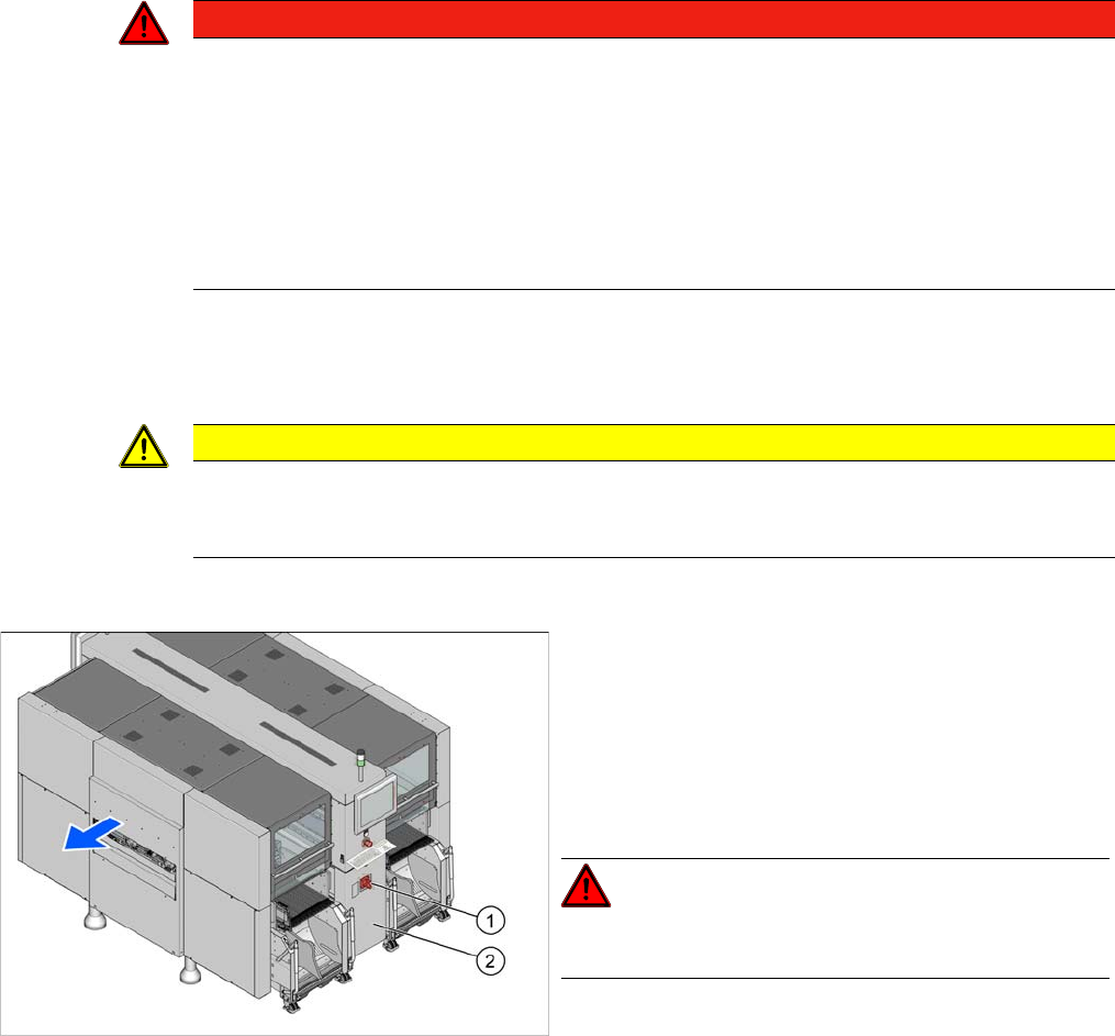
► End all placement operations on the machine.
► Switch the machine off at the main switch (1).
► Disconnect the machine from the main power supply.
► Open the lock on the power supply cover (2).
► Pull the power supply out towards the front.
► Reconnect the machine to the power supply.
DANGER!
Careful: there may be dangerous touch voltages in the vi-
cinity of the open power supply!
► Switch the placement machine on again at the main
switch and start it up.
Service Work
Electrical System 3.2.3 Checking the Input Voltage at the Inrush Current Limitation Board
38 Service Manual SIPLACE SX4/DX4
3.2.3
3.2.3 Checking the Input Voltage at the Inrush Current Limitation Board
Checking the Input Voltage at the Inrush Current Limitation Board
Overview
Checking/setting
► Remove the protective cover on the boards. To do this, loosen the four screws on the side of the
cover.
► Check the jumper arrangement and correct if necessary.
Take note of the position of jumper J1 (see "6.1.2 Inrush Current Limitation Board Transformer (A1)
[03066830-xx]" [ ➙ 273]).
► Fit the protective cover back into place.
DANGER
Observe the safety instructions
There is a risk of dangerous touch voltages and short circuits occurring in inrush current limita-
tion boards which have been made accessible and are connected for measurement purposes
or bridging checks.
Nonobservance of these safety instructions may cause injury to personnel and damage to the
machine!
Measurements may only be performed by specially trained service technicians, with appropri-
ate qualifications and expertise.
► Observe the instructions in section "1.1.3 Safety Instructions for the Power Supply" [ ➙ 10].
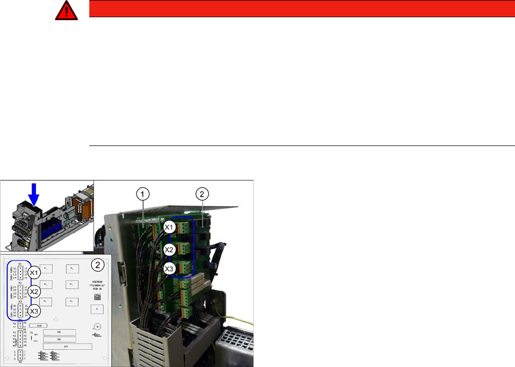
1. Inrush current limiter board - servo unit (with three
connectors) (A3)
2. Inrush current limiter board - transformer (with six
connectors) (A2)
X1, X2, X3: connectors for configuring the inrush current
limitation on the board (2)
The inrush current limitation board must be set to 400 V,
irrespective of the supply voltage. Use plug-in bridges for
this. Observe the label on the protective mesh cover.
Service Work
3.2.4 Checking the Input Voltage on the Transformer Module Electrical System
Service Manual SIPLACE SX4/DX4 39
3.2.4
3.2.4 Checking the Input Voltage on the Transformer Module
Checking the Input Voltage on the Transformer Module
Procedure
► Check the terminal panel, to make sure that the primary end of the three-phase transformer is con-
nected correctly for the required supply voltage.
The following overview shows the connection options for the primary voltages of the three-phase trans-
former:
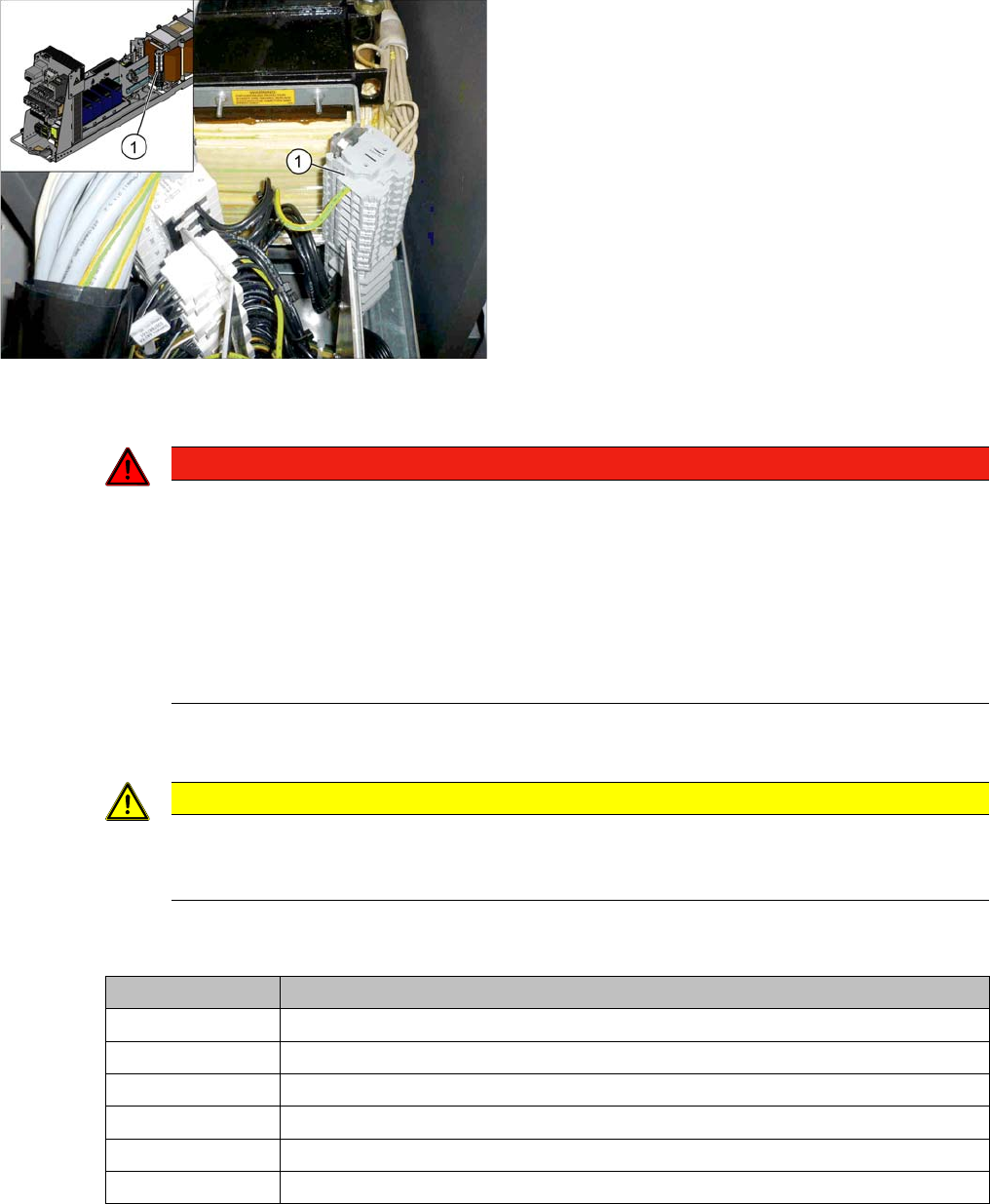
1. Terminal panels with primary connections for the
three-phase transformer
The primary end of the three-phase transformer needs to
be configured for the respective supply voltage.
DANGER
Observe the safety instructions
There is a risk of dangerous touch voltages and short circuits occurring in transformer modules
which have been made accessible and are connected for measurement purposes.
Nonobservance of these safety instructions may cause injury to personnel and damage to the
machine!
Measurements may only be performed by specially trained service technicians, with appropri-
ate qualifications and expertise.
► Observe the instructions in section "1.1.3 Safety Instructions for the Power Supply" [ ➙ 10].
CAUTION
Power supply networks in Japan and USA
The Japanese power supply network (3x 200 V~) and the power supply networks in the USA
(3x 208 V~) are connected to the terminals for 3x 204 V~.
Terminal panel Voltage
1U1, 1V1, 1W1 415 VAC
1U3, 1V3, 1W3 400 VAC
1U4, 1V4, 1W4 380 VAC
1U5, 1V5, 1W5 230 VAC
1U6, 1V6, 1W6 220 VAC
1U7, 1V7, 1W7 204 VAC