SIPLACE-SX4-DX4-用户手册.pdf - 第55页
Service Work 3.2.14 Replacing the SP Splitter (A10) [03076607-xx] Electrical System Service Manual SIPLACE SX4/DX4 55 3.2.14 3 . 2 . 1 4 R e p la c in g t h e S P S p lit t e r ( A 1 0 ) [ 0 3 0 7 6 6 0 7 - x x ] Replaci…
Service Work
Electrical System 3.2.13 Replacing the Socket [00375320-xx]
54 Service Manual SIPLACE SX4/DX4
3.2.13
3.2.13 Replacing the Socket [00375320-xx]
Replacing the Socket [00375320-xx]
Parts, Equipment and Tools
▪ Socket, rail-mounted SD-D/SC/LA/GY [00375320-xx]
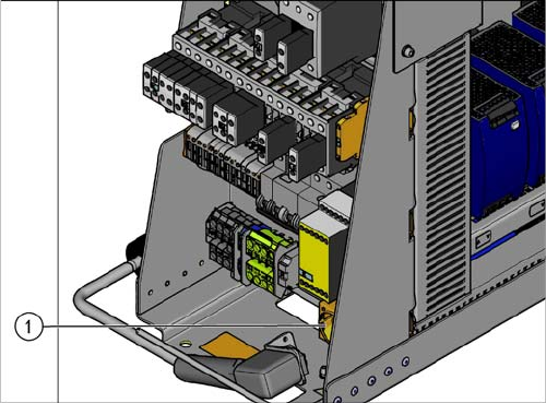
Overview
Removal
► Switch off the machine, disconnect it from the power supply and secure it to prevent unauthorized
reactivation. Observe the instructions in section "1.2 Preparatory Work..." [ ➙ 12].
► Unplug all connections to the socket. You may want to mark their positions, to make clear assign-
ment easier later on.
► Take the socket off the rail.
Installation
► Follow the removal instructions in reverse order for installation.
1. Socket
Service Work
3.2.14 Replacing the SP Splitter (A10) [03076607-xx] Electrical System
Service Manual SIPLACE SX4/DX4 55
3.2.14
3.2.14 Replacing the SP Splitter (A10) [03076607-xx]
Replacing the SP Splitter (A10) [03076607-xx]
Parts, Equipment and Tools
▪ SP splitter [03076607-xx]
▪ 12x microfuse 5x20/T6.3A/ceramic [03010626-xx] (supplied – see machine service box)
Overview
Removal
► Switch off the machine, disconnect it from the power supply and secure it to prevent unauthorized
reactivation. Observe the instructions in section "1.2 Preparatory Work..." [ ➙ 12].
► Loosen the screws fastening the mesh cover on the SP splitter and then remove the mesh cover.
► Unplug all electrical connections to the SP splitter. Mark their positions, to make clear assignment
easier later on.
► Loosen the screws fastening the SP splitter and then remove this.
Installation
► Follow the removal instructions in reverse order for installation.
1. SP splitter (A10)
Service Work
Electrical System 3.2.15 Replacing the Microfuse (F40 to F51) [03010626-xx]
56 Service Manual SIPLACE SX4/DX4
3.2.15
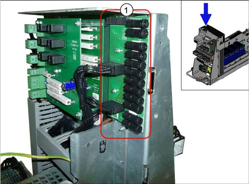
3.2.15 Replacing the Microfuse (F40 to F51) [03010626-xx]
Replacing the Microfuse (F40 to F51) [03010626-xx]
Parts, equipment and tools
▪ Microfuse 6.3A T / 150 VDC [03010626-xx]
Overview
Removal
► Use a suitable screwdriver to turn the fuse holder out of its socket.
► Remove the old microfuse from the fuse holder and replace this with a new microfuse of the same
type.
Installation
► Follow the removal instructions in reverse order for installation.
See also
5.2.1 Overview of Electrics [ ➙ 233]
NOTICE
Fuses
A fuse kit for the power supply is included with the delivery of the machine in a separate pack-
age or may be in the power supply.
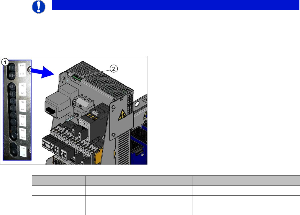
1. Microfuses F40 to F51
2. LED D40 to D51
The LEDs show the operational readiness of the individ-
ual microfuses.
Voltage Gantry 1 Gantry 2 Gantry 3 Gantry 4
+150V F40 F42 F43 F41
+42V F44 F46 F47 F45
+24V F48 F50 F51 F49