SIPLACE-SX4-DX4-用户手册.pdf - 第61页
Service Work 3.3.4 Replacing the BoxPC Memory Extension [030863 37-xx] Control Service Manual SIPLACE SX4/DX4 61 3.3.4 3 . 3 . 4 R e p la c in g t h e B o x P C M e m o r y E x t e n s io n [ 0 3 0 8 6 3 3 7 - x x ] Repl…
Service Work
Control 3.3.3 Replacing the Hotlink Interface Card [03052135-xx]
60 Service Manual SIPLACE SX4/DX4
3.3.3
3.3.3 Replacing the Hotlink Interface Card [03052135-xx]
Replacing the Hotlink Interface Card [03052135-xx]
Parts, equipment and tools
▪ Hotlink interface PCI-A24-K01 [03052135-xx]
Overview
The hotlink interface is installed in the BoxPC.
Removal/installation
► Removal and installation of the hotlink interface is identical to that for the CAN card (see "3.3.2 Re-
placing the CAN Card [03079973-xx]" [ ➙ 59]). Also observe the following instructions:
CAUTION
Hotlink interface power cable
The hotlink interface card is supplied without a hotlink interface power cable.
► You may need to order the hotlink interface power cable [03042074-xx]) separately.
CAUTION
Installation instructions
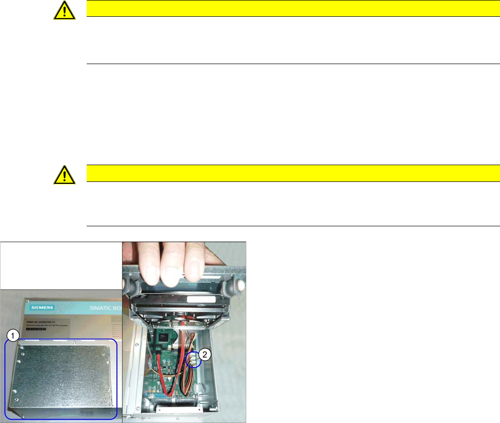
► Connect the "hotlink interface/power" cable [03042074-xx]. Follow the diagram below for
this.
Hotlink cable
► If you are replacing the hotlink interface power cable
(2), you will need to loosen and open the cover (1) on
the hard drives.
However, if you are continuing to use the old hotlink
interface power cable, this step is not required.
Service Work
3.3.4 Replacing the BoxPC Memory Extension [03086337-xx] Control
Service Manual SIPLACE SX4/DX4 61
3.3.4
3.3.4 Replacing the BoxPC Memory Extension [03086337-xx]
Replacing the BoxPC Memory Extension [03086337-xx]
Parts, equipment and tools
▪ Working memory SO-DIMM DDR2 667, 1024MB [03086337-xx]
Overview
Removal
► Switch off the machine, disconnect it from the power supply and secure it to prevent unauthorized
reactivation. Observe the instructions in section "1.2 Preparatory Work..." [ ➙ 12].
► Dismantle and remove the BoxPC from the machine.
(See Replacing the Control Computer BoxPC [03084494-xx])
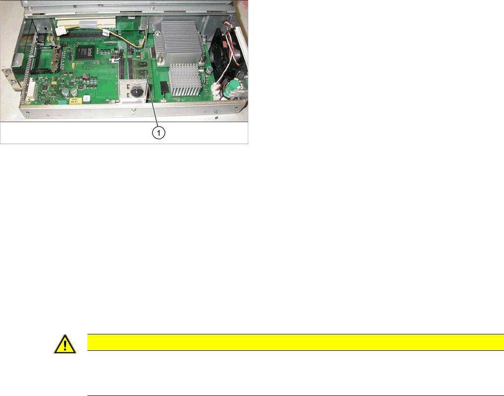
► Loosen the two screws fastening the cover of the BoxPC and open the cover.
► Loosen the locks on both sides of the memory extension and remove the memory extension.
Installation
► Follow the removal instructions in reverse order for installation. Also observe the following instruc-
tions:
See also
3.3.2 Replacing the CAN Card [03079973-xx] [ ➙ 59]
3.3.1 Replacing the Control Computer BoxPC [ ➙ 57]
1. Memory extension
CAUTION
Installation instructions
► Make sure that you insert the memory extension the right way round. The new memory ex-
tension must audibly engage into its slot.
Service Work
Control 3.3.5 Replacing the Monitor [03078913-xx]
62 Service Manual SIPLACE SX4/DX4
3.3.5
3.3.5 Replacing the Monitor [03078913-xx]
Replacing the Monitor [03078913-xx]
Parts, Equipment and Tools
▪ Monitor SCD1520-TDC [03078913-xx]
Overview
Removal
► Switch off the machine, disconnect it from the power supply and secure it to prevent unauthorized
reactivation. Observe the instructions in section "1.2 Preparatory Work..." [ ➙ 12].
► Unplug all connections to the monitor. You may want to mark their positions, to make clear assign-
ment easier later on.
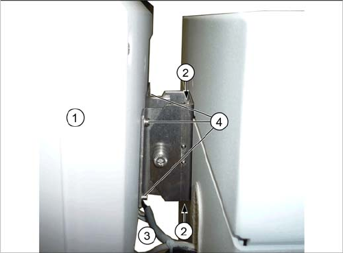
► Loosen the upper and lower screws fastening the monitor bracket to the machine and lift the monitor
and its bracket out of the keyholes.
► Loosen the four screws fastening the monitor to its bracket. You will need the monitor bracket when
fitting the new monitor.
Installation
► Follow the removal instructions in reverse order for installation.
1. Monitor
2. Screws fastening the monitor bracket to the machine
3. Monitor connections
4. Screws fastening the monitor to the bracket