SIPLACE-SX4-DX4-用户手册.pdf - 第63页
Service Work 3.4.1 Pneumatic System - Overview Pneumatic System Service Manual SIPLACE SX4/DX4 63 3.4 3 . 4 P n e u m a t ic S y s t e m Pneumatic System Pneumat ic System - Using th e Correc t Blanking Plugs 3.4.1 3 . 4…
Service Work
Control 3.3.5 Replacing the Monitor [03078913-xx]
62 Service Manual SIPLACE SX4/DX4
3.3.5
3.3.5 Replacing the Monitor [03078913-xx]
Replacing the Monitor [03078913-xx]
Parts, Equipment and Tools
▪ Monitor SCD1520-TDC [03078913-xx]
Overview
Removal
► Switch off the machine, disconnect it from the power supply and secure it to prevent unauthorized
reactivation. Observe the instructions in section "1.2 Preparatory Work..." [ ➙ 12].
► Unplug all connections to the monitor. You may want to mark their positions, to make clear assign-
ment easier later on.
► Loosen the upper and lower screws fastening the monitor bracket to the machine and lift the monitor
and its bracket out of the keyholes.
► Loosen the four screws fastening the monitor to its bracket. You will need the monitor bracket when
fitting the new monitor.
Installation
► Follow the removal instructions in reverse order for installation.
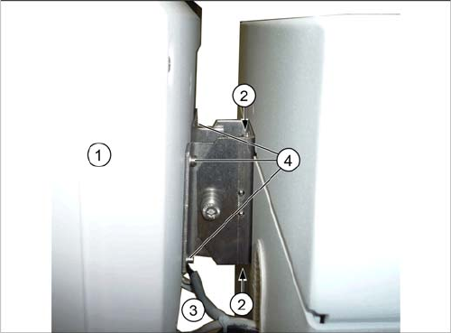
1. Monitor
2. Screws fastening the monitor bracket to the machine
3. Monitor connections
4. Screws fastening the monitor to the bracket
Service Work
3.4.1 Pneumatic System - Overview Pneumatic System
Service Manual SIPLACE SX4/DX4 63
3.4
3.4 Pneumatic System
Pneumatic System
Pneumat ic System - Using th e Correc t Blanking Plugs
3.4.1
3.4.1 Pneumatic System - Overview
Pneumatic System - Overview
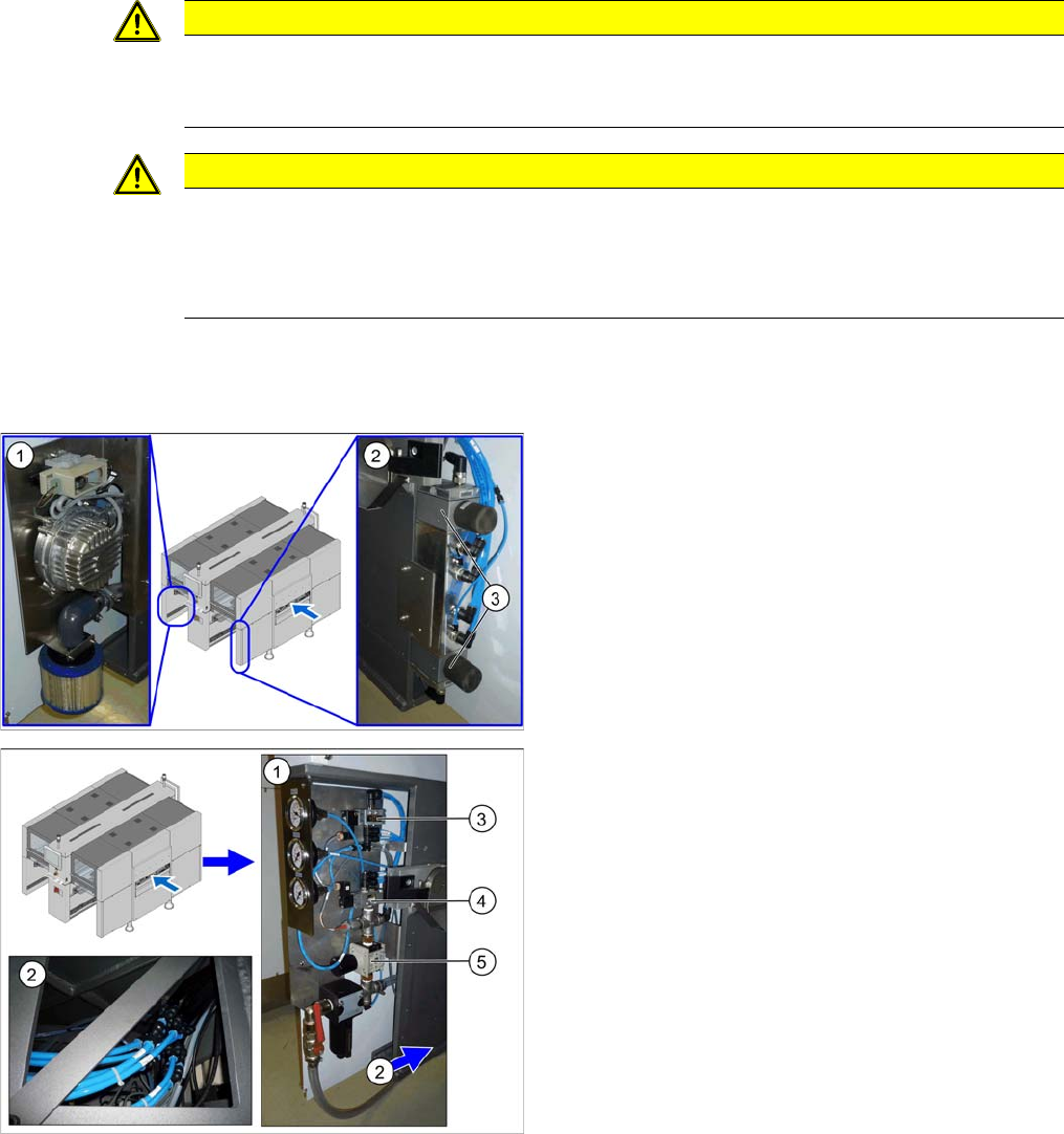
The pneumatic system is located at locations 1, 3 and 4, behind the side covers.
CAUTION
Switch off the compressed air supply.
When working on the pneumatic system, always disconnect the machine from the compressed
air supply.
CAUTION
Use the correct blanking plugs
► Only use blanking plugs in the machine which match the manufacturer's compressed air
connection. A tight fit cannot be guaranteed for other blanking plugs.
► We recommend the use of blanking plugs made by Festo.
1. Location 3, behind the side cover: Elmo blower with
electrics, cooling air filter
2. Location 4, behind the side cover
3. Proportional controller for gantry group of placement
heads PA1/PA2
1. Location 1, behind the side cover: connection cou-
pling, main valve with compressed air filter, com-
pressed air displays
2. Location 1, at the bottom, in the machine base: com-
pressed air connection for gantry trailing cable and
vacuum pump option
3. 5/2 way valve [03062277-xx]
Main valve (X59) for NC, input, conveyor
4. 5/2 solenoid valve [00344974-xx]
Safety valve (X60) for tape cutter
5. Pressure regulator [03062103-xx]
Service Work
Pneumatic System 3.4.2 Sealing the Screwed Connections
64 Service Manual SIPLACE SX4/DX4
3.4.2
3.4.2 Sealing the Screwed Connections
Sealing the Screwed Connections
3.4.3
3.4.3 Dismantling the Lower Side Cover
Dismantling the Lower Side Cover
NOTICE
Sealing the Screwed Connections
If compressed air screwed connections are loosened, these will need to be sealed again after-
wards. Always use the same sealing technique as was used before they were removed.
There are several different sealing techniques:
► Sealing ring (rubber or plastic)
These are either supplied or you can use the ones used before. Check the condition of the
sealing rings for damage.
► Sealant
There are several variants of this:
Loctite 567 [03097172-xx] and Loctite 55 [03092492-xx] – after loosening the connection,
clean the screwed thread and seal it with Loctite. The sealing thread for Loctite 55 must be
wound on in the direction of the screwed thread.
There may also already be a sealant on the screwed thread.
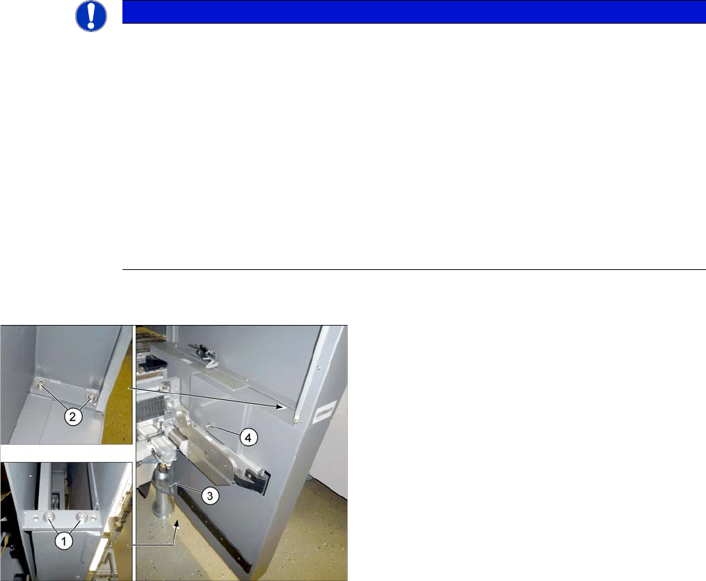
Most tasks performed on the pneumatic system require
that you dismantle the lower side cover.
► To do this, loosen the 6 screws fastening the side
cover in the order (1) to (4) and remove these. While
unscrewing, always hold on to the side cover, to pre-
vent it falling off.
► Carefully pull out the side cover.