SIPLACE-SX4-DX4-用户手册.pdf - 第79页
Service Work 3.5.5 Replacing the Trailing Cable Gantries Service Manual SIPLACE SX4/DX4 79 Preparation In accordance with your machine' s configuration, you will need to remo ve the relevant modules, covers and cove…
Service Work
Gantries 3.5.5 Replacing the Trailing Cable
78 Service Manual SIPLACE SX4/DX4
3.5.5
3.5.5 Replacing the Trailing Cable
Replacing the Trailing Cable
▪ Trailing cable SIPLACE SX4/DX4 2P G [03078380-xx] for gantry 2 and 4
or
Trailing cable SIPLACE SX4/DX4 2P U [03078376-xx] for gantry 1 and 3
3.5.5.1
3.5.5.1 Introduction
Introduction
This manual sometimes uses diagrams of the SIPLACE HF machine. However, this does not affect the
removal or installation work for the SX4/DX4. If there are any differences which need to be taken into
account, these will be indicated separately.
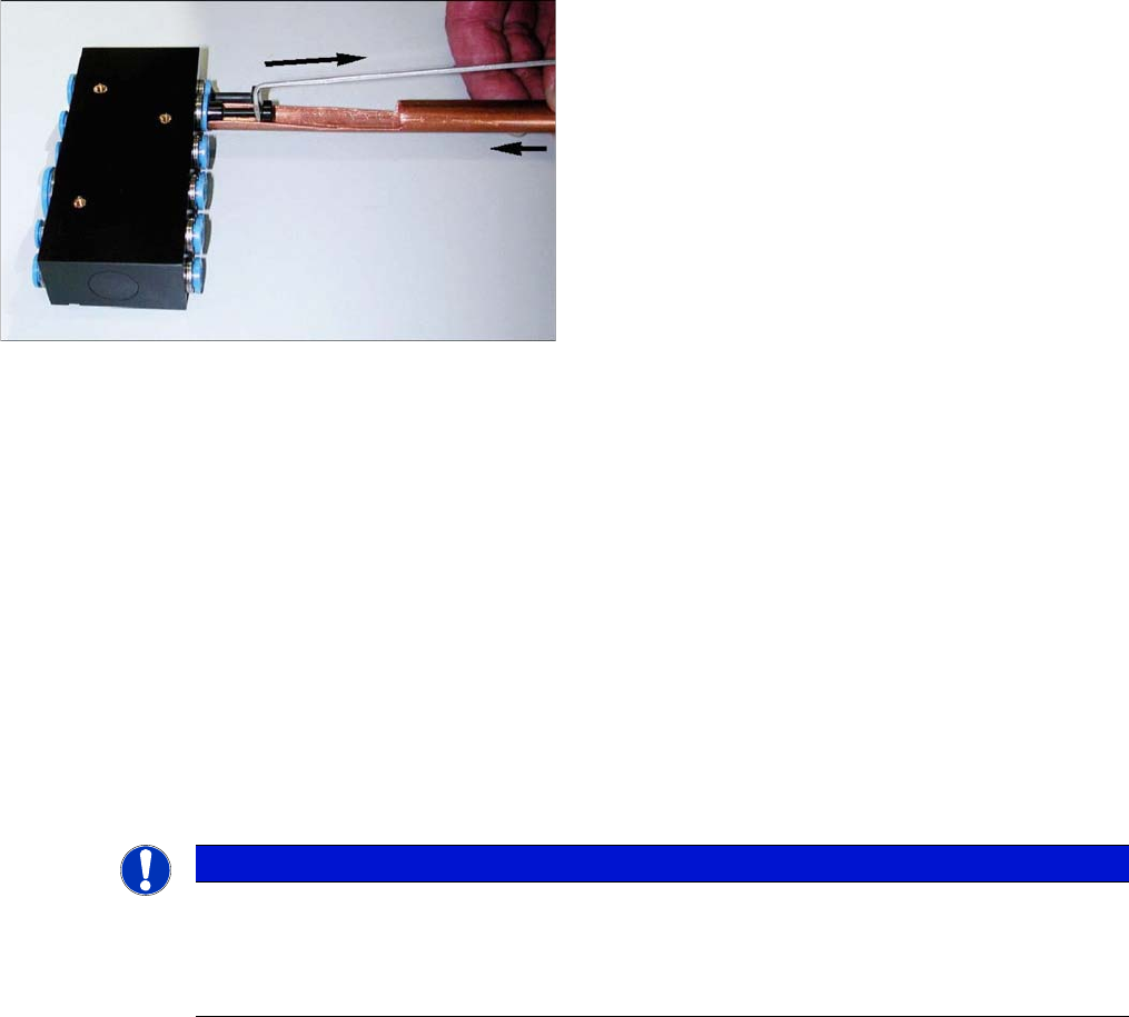
Handling the Hose Unlocking Tool [03047090-xx]
► Use the pipe-shaped tool (1) to open the unlocking ring.
► Carefully pull the hose out of the compressed air connection. The diagram shows the removal of a
dummy plug (2), not a hose.
3.5.5.2
3.5.5.2 Replacing the Trailing Cable for SX4 Machines
Replacing the Trailing Cable for SX4 Machines
Parts, Equipment and Tools
▪ Hose pliers for cutting the pneumatic hose
▪ Hose unlocking tool [03047090-xx]
▪ Pipe/hose cutters [00381443-01]
▪ Retrofitting guide "Vacuum pump on SX4/DX4" [00196845-xx] - if required
▪ Sealing varnish Loctite 241 [02101037-xx]
You will need to order the following parts separately:
▪ Gauge for trailing cable (for gantry 1 and 3 - X4i/SX4/DX4) [00383029-xx]
▪ Gauge for trailing cable (for gantry 2 and 4 - X4i/SX4/DX4) [03063762-xx]
▪ Edding marker, white [00382740-xx]
▪ Press-fit connection QS-6 [03049770-xx] (these are included in the trailing cable package with S
number)
Due to the poor access to the pneumatic distributor, we
recommend using an unlocking tool.
With the help of the hose unlocking tool [03047090-xx]
you can open the unlocking ring (blue here) for the com-
pressed air connection. This enables you to remove both
the hoses and the dummy plugs (additional tool "Unlock-
ing tool for QSC-10H" [03051853-xx]).
NOTICE
No gauge
If there is no gauge available, you can proceed as follows:
► Place the old and new trailing cables next to one another and adjust the length of the new
trailing cable hose. Match the hose lengths to the old trailing cable.
Service Work
3.5.5 Replacing the Trailing Cable Gantries
Service Manual SIPLACE SX4/DX4 79
Preparation
In accordance with your machine's configuration, you will need to remove the relevant modules, covers
and cover plates before you can dismantle the trailing cable.
► Where necessary, remove the cover plates from the gantry trailing cable. Mark their exact position
to ensure correct replacement later.
► Remove the top central cover from the SIPLACE machine.
► Remove the upright covers over the trailing interface gantry, so that you can reach the trailing cable.
Preparing the Trailing Cable
Handling and overview of gauge
The trailing cable is supplied as a complete assembly.
The pneumatic hoses need to be shortened to the exact length of the distance to the pneumatic distrib-
utor on the head mount and in the machine. Use the gauge to help you with this. The existing pneumatic
hoses, which are run in the machine, need to be cut through and connected to the trailing cable at the
exact position, with the help of hose couplings [03049770-01] provided.
There are two gauges available, for the different gantries.
▪ Gauge for trailing cable (for gantry 1 and 3 - X4i/SX4/DX4) [00383029-01]
▪ For the rotated gantry 2 and 4 only - X4i/SX4/DX4:
gauge for trailing cable (for gantry 2 and 4 - X4I) [03063762-01]
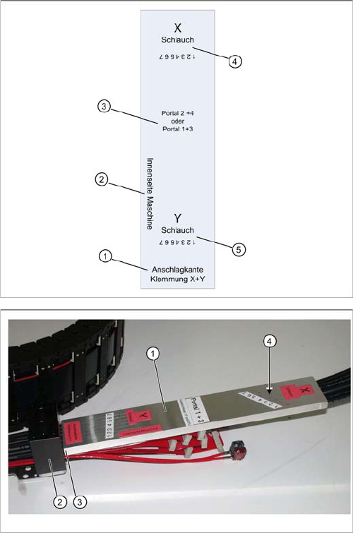
► Observe the designation for the respective gantry on the gauge (1) (gantry 1+3 or gantry 2+4). Se-
lect the correct gauge.
► Place the stopper edge (3) of the gauge (see mark labeled edge for clamp X+ Y on the gauge) at the
edge of the clamping plate (2) for the X trailing cable.
The gauges are labeled to ensure correct handling.
1. Stopper edge for clamp X and Y: this side of the
gauge must be attached to the respective trailing ca-
ble clamp.
2. Machine inside: this side of the gauge must point to
the inside of the machine.
3. Gauge designations
4. X hose: this is where you see the 7 drillings for the X
hose markings.
5. Y hose: this is where you see the 7 drillings for the Y
hose markings.
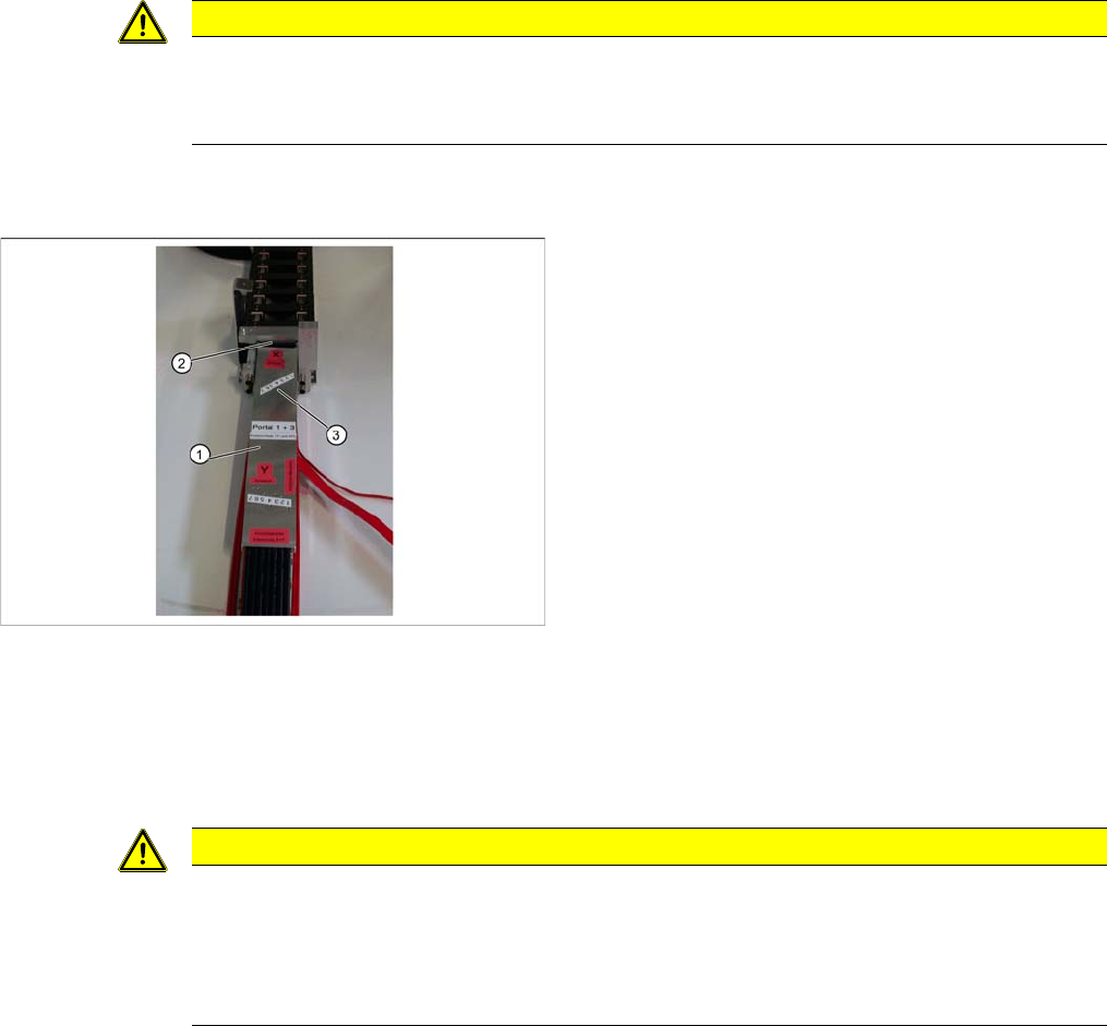
Shortening X hoses at the X trailing cable clamp (to the
pneumatic distributor at the head mount)
1. Gauge for shortening the hoses
2. X trailing cable clamp
3. Stopper edge (gauge at clamp)
4. Hose marking
Service Work
Gantries 3.5.5 Replacing the Trailing Cable
80 Service Manual SIPLACE SX4/DX4
► Mark the pneumatic hoses through the holes (4) in the gauge. Observe the position labeled X hose.
► Use the hose pliers to cut the pneumatic hoses at the marked position. The pneumatic hoses can
now be run inside the pneumatic distributor, with the correct curvature.
► Observe the designation for the respective gantry on the gauge (1) (gantry 1+3 or gantry 2+4). Se-
lect the correct gauge.
► Place the stopper edge (2) of the gauge (see mark labeled edge for clamp X +Y on the gauge) at the
edge of the clamp for the Y axis.
► Mark the pneumatic hoses through the holes (3) in the gauge.
► Use the hose pliers to cut the pneumatic hoses at the marked position. The pneumatic hoses should
now have the correct length and can be connected to the severed pneumatic hoses in the machine
base.
CAUTION
Mark the correct position!
► Observe the position labeled X hose.
► Observe the position marked machine inside on the gauge.
Shortening the Y hoses to the pneumatic distributor in the
machine base
1. Gauge for shortening the hoses
2. Stopper edge at the machine base clamp
3. Hose marking
CAUTION
Mark the correct position!
► Observe the position labeled Y hose.
► To ensure that they have the correct length, cut the pneumatic hoses at the marking labeled
"Y hose". If the pneumatic hoses are cut too short, you will have to discard the entire trailing
cable.