SIPLACE-SX4-DX4-用户手册.pdf - 第84页
Service Work Gantries 3.5.5 Replacing the Trailing Cable 84 Service Manual SIPLACE SX4/DX4 ► Remove t he hoses from the pneumatic distributor (7) . ► Undo the 4 scre ws (6 ) fastening the trailing cable co nsole and care…
Service Work
3.5.5 Replacing the Trailing Cable Gantries
Service Manual SIPLACE SX4/DX4 83
To sever the pneumatic hoses, which lead to the pneu-
matic distributor inside the machine base, proceed as fol-
lows:
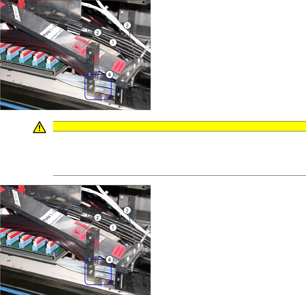
► Place the gauge (1) on the mount (3).
► Use the gauge to label the hoses at the Y hose mark
(2). You will need a "white Edding paint marker pen"
for this.
► Disconnect the cooling tubes for the Y motor from the
connection piece (4) (machine base).
CAUTION
Before cutting the pneumatic hoses
► Label the order of pneumatic hoses as shown on the gauge (from 1 to 7 – inside to outside).
This is important to ensure that the hoses are then correctly connected again after cutting.
► During cutting, make sure that the pneumatic hoses do not fall into the machine base. Se-
cure them accordingly.
► Loosen the outer screws fastening the trailing cable
mount (3).
► If the option "Vacuum pump" is available, loosen the
pneumatic hoses (2) and follow the instructions in the
"Vacuum pump SX4/DX4 assembly instructions"
[00196845-xx].
► Secure the end of the trailing cable (with cable ties) in
the machine to prevent it hanging loosely and damag-
ing other machine components.
Service Work
Gantries 3.5.5 Replacing the Trailing Cable
84 Service Manual SIPLACE SX4/DX4
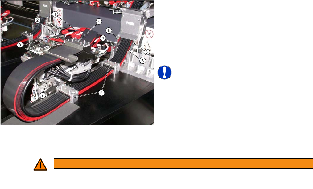
► Remove the hoses from the pneumatic distributor (7).
► Undo the 4 screws (6) fastening the trailing cable console and carefully remove the complete trailing
cable from the machine. The fastening screws have been secured with Loctite.
► When you replace an old trailing cable with a new one, you also need to remove the hotlink card
(including fixtures) and the Vision board spread spectrum.
Gantry (using example of X series)
► Disconnect the flat ribbon cable (1) from the head
board (2).
► Disconnect the camera cable (3) from the head board
(2).
► Undo the outer screws fastening the X trailing cable
clamp (4) and the two clamps (5) on the back of the
gantry.
NOTICE!
Clamp remains intact
Only loosen the fastening screws. The clamps for the flat
ribbon cable remain in place.
Mark the installation position of the contact disks and
spacer bolts and take care not to lose them. These will
need to be correctly replaced later.
WARNING
Risk of injury to hands
► Use the hose unlocking tool to remove the hoses [03047090-xx].
Service Work
3.5.5 Replacing the Trailing Cable Gantries
Service Manual SIPLACE SX4/DX4 85
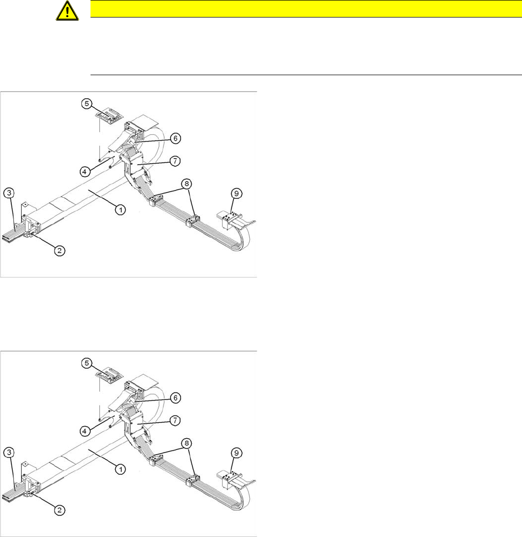
Installation
► Carefully insert the new trailing cable (1) into the prescribed position. Make sure you do not twist it.
► Temporarily fasten the ends to the machine base (e.g. by tying them).
► Fit the gantry interface board (5) onto the holder (4) of the new trailing cable.
► Reconnect all compressed air connections at the pneumatic distributor. Observe the correct con-
nector assignment.
► The pneumatic hoses need to be shortened to the optimum length, with the help of the gauge. See
also "3.5.5.2.3 Preparing the Trailing Cable" [ ➙79]. They must engage firmly but should not be fold-
ed over.
► Loosely screw in the clamps (8) and (9).
► Check that the power track chain can run along the top of the machine base without obstruction.
Move the Y axis back and forth to check this.
► If necessary, correct at the trailing cable console (7) and at the clamps (8) and (9).
► Fix the two clamps (8) and (9) and the trailing cable console (7). Use Loctite 241 to secure them.
► Tighten the fastening screws for the trailing cable console (7) crosswise.
CAUTION
Always handle the trailing cable with care
Handle the new trailing cable with care and enlist the help of a second person.
Make sure that the flat ribbon cable and the pneumatic hoses are not rubbed against any parts
or folded. Look out for sharp edges.
1. Complete trailing cable unit
2. Mount
3. Pneumatic hoses (shorten to optimum length with
gauge)
4. Gantry interface bracket
5. Gantry interface
6. Connection piece for cooling tubes to Y motor
7. Trailing cable console
8. Clamp at back of gantry
9. X trailing cable clamp
► Loosely fasten the trailing cable console (7) with a
screw.
► Clean the trailing cable contact surface on the ma-
chine base with a dry cloth.
► Starting from the trailing cable console (7), run all ca-
bles and hoses to the appropriate connections:
► Reconnect all electrical connections at the head
board. Observe the correct connector assignment.
► Reestablish all connections to the hotlink card and
the Vision board spread spectrum.