SIPLACE-SX4-DX4-用户手册.pdf - 第90页
Service Work Gantries 3.5.11 Replacing the GCU [03052200 - xx] 90 Service Manual SIPLACE SX4/DX4 3.5.11 3 . 5 . 1 1 R e p la c in g t h e G C U [ 0 3 0 5 2 2 0 0 - x x ] Replacing the GCU [03052200 - xx] Parts, equipment…
Service Work
3.5.10 Replacing the Gantry Interface Gantries
Service Manual SIPLACE SX4/DX4 89
3.5.10
3.5.10 Replacing the Gantry Interface
Replacing the Gantry Interface
Parts, Equipment and Tools
▪ Gantry interface gantry 1 and 3 [03059908-xx]
▪ Gantry interface gantry 2 and 4 [03059909-xx]
Overview
Removal
► Switch off the machine, disconnect it from the power supply and secure it to prevent unauthorized
reactivation. Observe the instructions in section "1.2 Preparatory Work..." [ ➙ 12].
► Unplug the electrical connections to the gantry interface. You may want to mark their positions, to
make clear assignment easier later on.
► Loosen the two screws fastening the gantry interface and remove the interface from the machine.
Installation
► Follow the removal instructions in reverse order for installation.
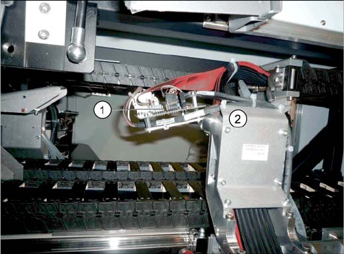
1. Gantry interface
2. Trailing cable holder on gantry
Service Work
Gantries 3.5.11 Replacing the GCU [03052200-xx]
90 Service Manual SIPLACE SX4/DX4
3.5.11
3.5.11 Replacing the GCU [03052200-xx]
Replacing the GCU [03052200-xx]
Parts, equipment and tools
▪ Positioning control for the gantry axes GCU [03052200-xx]
Overview
Removal
► Switch off the machine, disconnect it from the power supply and secure it to prevent unauthorized
reactivation. Observe the instructions in section "1.2 Preparatory Work..." [ ➙ 12].
► Unplug all connections on the GCU. You may want to mark their positions, to make clear assignment
easier later on.
► Loosen the screws fastening the mount and then remove the mount.
► Remove the GCU from the machine.
Installation
► Follow the removal instructions in reverse order for installation. Also observe the following instruc-
tions:
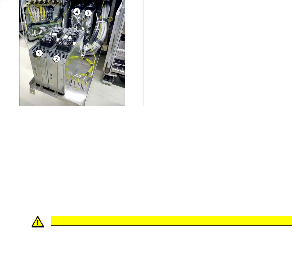
1) to 4) GCUs
The GCUs are located in a rack unit between locations 1
and 2.
The assignment of GCUs to gantries differs according to
the machine type. Observe the instructions in section
"5.4.7 Overview of GCUs" [ ➙ 247].
CAUTION
Installation instructions
► Use the DIP switch to set the gantry ID on the GCU. (see "5.4.7 Overview of GCUs"
[ ➙ 247]).
► Check the firmware and perform a download, if needed. (see "5.8.1 Firmware Download
(SW 70x)" [ ➙ 266]).
Service Work
3.5.12 Replacing the GCU Fan [03060954-xx] Gantries
Service Manual SIPLACE SX4/DX4 91
3.5.12
3.5.12 Replacing the GCU Fan [03060954-xx]
Replacing the GCU Fan [03060954-xx]
Parts, equipment and tools
▪ GCU fan [03060954-xx]
Overview
Removal
► Switch off the machine, disconnect it from the power supply and secure it to prevent unauthorized
reactivation. Observe the instructions in section "1.2 Preparatory Work..." [ ➙ 12].
► Unplug the electrical connection to the fan. You may want to mark the position of this connection, to
make clear assignment easier later on.
► Pull out the four expansion rivets on the fan and then remove the fan.
Installation
► Follow the removal instructions in reverse order for installation. Also observe the following instruc-
tions:
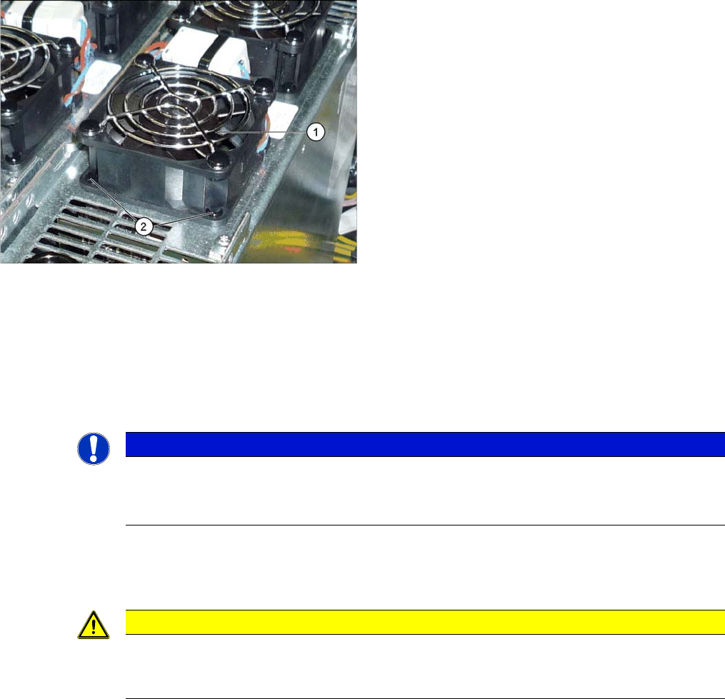
1. Fan on the GCU
2. Plastic expansion rivets
(snap rivet DRM 4x4,5-5.5 sw SR-4070B [03106012-
xx])
These are supplied with the fan.
NOTICE
Two-part expansion rivets
The expansion rivets are in two parts.
► First remove the center pin. The lower part can now be easily pulled out.
CAUTION
Installation instructions
► The expansion rivets are in two parts. First insert the lower part into the hole and then fix
this into place with the upper part.