SIPLACE-SX4-DX4-用户手册.pdf - 第93页
Service Work 3.5.13 Replacing the Head Adapter for the HCU and the HCU Gantries Service Manual SIPLACE SX4/DX4 93 Converting the HCU If you have ordered the base adapter without HCU(s) you will ha ve to co nvert the H CU…
Service Work
Gantries 3.5.13 Replacing the Head Adapter for the HCU and the HCU
92 Service Manual SIPLACE SX4/DX4
3.5.13
3.5.13 Replacing the Head Adapter for the HCU and the HCU
Replacing the Head Adapter for the HCU and the HCU
Parts, equipment and tools
You can replace either the base adapter alone, the HCU alone or the base adapter together with the
HCU.
The following spare parts/kits can be replaced:
▪ Module X basic adapter C&P [03071420-xx]
Consists of: 1x PCB/X basic adapter C&P [03045647-xx], 1x HCU assembly [03054884-xx]
▪ MHCU assembly compatible [03090990-xx] (replaces: HCU assembly [03054884-xx])
▪ PCB/X base adapter C&P [03045647-xx]
▪ Module/X base adapter TWIN [03062201-xx]
Removal
► Switch off the machine, disconnect it from the power supply and secure it to prevent unauthorized
reactivation. Observe the instructions in section "1.2 Preparatory Work..." [ ➙ 12].
► You may need to dismantle the placement head for
better access. Read the relevant chapter, section
Placement heads, if required.
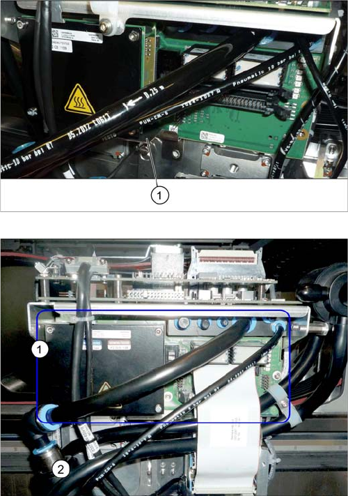
► Loosen the two screws fastening the protective
plate (1) (if present) and remove the protective plate.
Head adapter HCU (example of C&P20A version on an
SX4 shown )
► Unplug all electrical connections to the head
adapter (1). You may want to mark their positions, to
make clear assignment easier later on.
Service Work
3.5.13 Replacing the Head Adapter for the HCU and the HCU Gantries
Service Manual SIPLACE SX4/DX4 93
Converting the HCU
If you have ordered the base adapter without HCU(s) you will have to convert the HCU(s). Proceed as
follows:
► Repeat this procedure for the second HCU, if necessary (for TwinHead only).
Installation
► Follow the removal instructions in reverse order for installation. Also observe the following instruc-
tions:
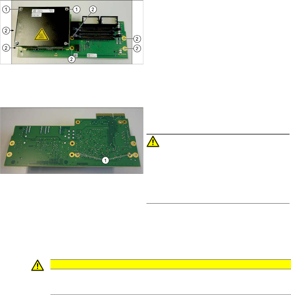
► Loosen the screws (2) fastening the board.
► In addition, the board is fastened with the topmost of
both HCU screws (1). You also need to loosen this.
► Carefully pull the board down and off.
Make sure that the head adapter board is connected
to the head interface via a press-fit connection from
below.
► Loosen the two screws fastening the HCU on the
back of the board and carefully pull the HCU off the
base adapter.
CAUTION!
Washers and pins
Make sure that you do not lose the washers. Make a note
of the number of washers used for each screw, as this
may well differ. These will need to be fitted back in again
as well.
Make sure that you do not damage the pins under the
HCU.
CAUTION
Installation instructions
► Check the firmware and perform a download, if needed. (See "5.8.1 Firmware Download
(SW 70x)" [ ➙ 266])
Service Work
Gantries 3.5.14 Installation Positions on the Head Plate
94 Service Manual SIPLACE SX4/DX4
3.5.14
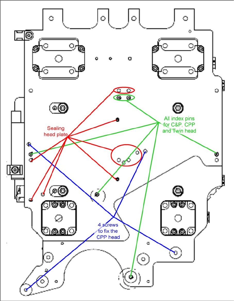
3.5.14 Installation Positions on the Head Plate
Installation Positions on the Head Plate