Manuelles Tray an D1 an Stellplatz 2.pdf - 第23页
Special Design 2 Assembly instructions Special des ign for manual tray at location 2 SIPLACE D1 05/2007 Edition 23 : S tick the SOKO label on the right cover . : Check the cable routing fr om the limit switches. : Switch…
2 Assembly instructions Special design for manual tray at location 2 SIPLACE D1 Special Design
05/2007 Edition
22
: Disassemble the limit switch from the bracket.
: Assemble the new bracket for the limit switches using the screws you removed before.
2
Use only the upper screws to assemble the new bracket so that you still can turn the bracket to
assemble the covers for the conversion boards. 2
2
: Assemble the left limit switch on the new bracket at the left side of the output conveyor.
: Assemble the right limit switch on the new bracket at the right side of the output conveyor so
that the side panel from the conveyor can not crash with the tray holder.
2
: Currently the cable is routed underneath the cover from the conversion board.
Route the cable from the right limit switch underneath the right or left cover from the conversion
board to the notch from this cover.
2
2
: Assemble the covers from the conversion board.
: Fix the new bracket with the other two screws and tighten all screws from the new bracket.
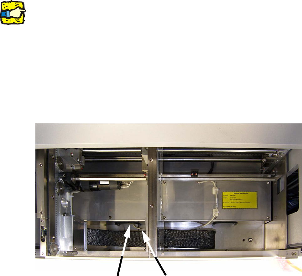
: Locate the cable approximately in the middle of the right cover from the conversion board with
two self-adhesive cable clamps. Clean the surface before with ethyl alcohol and a lint-free
cloth.
Notch
Cable routing

Special Design 2 Assembly instructions Special design for manual tray at location 2 SIPLACE D1
05/2007 Edition
23
: Stick the SOKO label on the right cover.
: Check the cable routing from the limit switches.
: Switch on the placement machine and change to the SITEST.
: Adjust both limit switches and test the conveyor width adjustment and the function of the limit
switches.
2.8 Disassembly of the hardware
The disassembly has to be done in reverse direction. 2
2.9 Programming under SIPLACE Pro
2
For programming under SIPLACE Pro, use the instructions „Programming guide for arbitrary car-
rier under SIPLACE Pro“ (item no.: 00194607-xx). 2
2
2.10 Possible causes of error
Pick-up problems 2
– The trays were not fixed using the magnets provided.
Solution: Fix the trays again.
– The trays are not described correctly in SIPLACE Pro.
Solution: Correct the tray description.
– Placement head picks up at a wrong place.
Solution: Determine offset values using the Arbitrary Carrier instructions and enter correct val-
ues.
– The trays have no or wrong offset values.
Solution: Determine the right offset values (see instructions).
– Tray holder was not fitted correctly.
Solution: Tighten all the screws.
– The trays are not fixed without stress using the magnets provided.
Solution: Fix the trays again.
2 Assembly instructions Special design for manual tray at location 2 SIPLACE D1 Special Design
05/2007 Edition
24