GST 8000E曲线锯说明书.pdf - 第7页
English | 7 Bosch Power Tools 1 609 92A 41J | (27.9.17) Selecting a Saw Blade An overview of recommend ed saw blades can be found at the end of these instructions. Use only T-shank saw blad es. The saw blade should not b…
6 | English
1 609 92A 41J | (27.9.17) Bosch Power Tools
Safety Warnings for Jigsaws
Hold power tool by insulated gripping surfaces, when
performing an operation where the cutting accessory
may contact hidden wiring or its own cord. Cutting
accessory contacting a “live” wire may make exposed
metal parts of the power tool “live” and could give the
operator an electric shock.
Keep hands away from the sawing range. Do not reach
under the workpiece. Contact with the saw blade can
lead to injuries.
Apply the machine to the workpiece only when
switched on. Otherwise there is danger of kickback when
the cutting tool jams in the workpiece.
Pay attention that the base plate 5 rests securely on
the material while sawing. A jammed saw blade can
break or lead to kickback.
When the cut is completed, switch off the machine and
then pull the saw blade out of the cut only after it has
come to a standstill. In this manner you can avoid kick-
back and can place down the machine securely.
Use only undamaged saw blades that are in perfect
condition. Bent or dull saw blades can break, negatively
influence the cut, or lead to kickback.
Do not brake the saw blade to a stop by applying side
pressure after switching off. The saw blade can be
damaged, break or cause kickback.
Use suitable detectors to determine if utility lines are
hidden in the work area or call the local utility company
for assistance. Contact with electric lines can lead to fire
and electric shock. Damaging a gas line can lead to explo-
sion. Penetrating a water line causes property damage or
may cause an electric shock.
Secure the workpiece. A workpiece clamped with clamp-
ing devices or in a vice is held more secure than by hand.
Always wait until the machine has come to a complete
stop before placing it down. The tool insert can jam and
lead to loss of control over the power tool.
Products sold in GB only: Your product is fitted with a
BS 1363/A approved electric plug with internal fuse
(ASTA approved to BS 1362).
If the plug is not suitable for your socket outlets, it should
be cut off and an appropriate plug fitted in its place by an
authorised customer service agent. The replacement plug
should have the same fuse rating as the original plug.
The severed plug must be disposed of to avoid a possible
shock hazard and should never be inserted into a mains
socket elsewhere.
Product Description and
Specifications
Read all safety warnings and all instruc-
tions. Failure to follow the warnings and in-
structions may result in electric shock, fire
and/or serious injury.
Intended Use
The machine is intended for making separating cuts and cut-
outs in wood, plastic, metal, ceramic plates and rubber while
resting firmly on the workpiece. It is suitable for straight and
curved cuts with mitre angles to 45°. The saw blade recom-
mendations are to be observed.
Product Features
The numbering of the product features refers to the
illustration of the machine on the graphics page.
1 Lock-on button for On/Off switch
2 Thumbwheel for stroke rate preselection
3 On/Off switch
4 Hex key
5 Base plate
6 Adjusting lever for orbital action
7 Guide roller
8 Saw blade*
9 Contact protector
10 Handle (insulated gripping surface)
11 Stroke rod
12 SDS clamping lever for saw blade release
13 Splinter guard
14 Scale for mitre angle
15 Screw
*Accessories shown or described are not part of the standard de-
livery scope of the product. A complete overview of accessories
can be found in our accessories program.
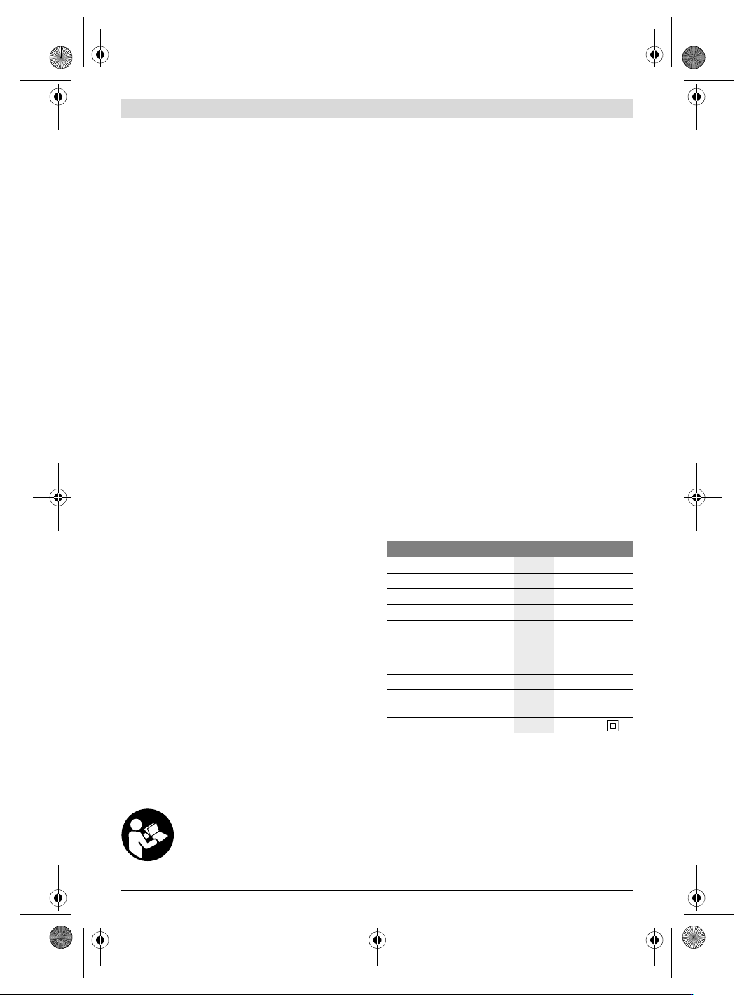
Technical Data
Assembly
Before any work on the machine itself, pull the mains
plug.
Replacing/Inserting the Saw Blade
When mounting the saw blade, wear protective gloves.
Danger of injury when touching the saw blade.
Jigsaw GST 8000 E
Article number
3 601 E8H 0..
Rated power input
W710
Stroke rate at no load n
0
min
-1
800–3100
Stroke
mm 20
Cutting capacity, max.
–in wood
–in aluminium
– in non-alloy steel
mm
mm
mm
80
20
10
Bevel cuts (left/right), max.
°45
Weight according to
EPTA-Procedure 01:2014
kg 2.5
Protection class
/II
The values given are valid for a nominal voltage [U] of 230 V. For differ-
ent voltages and models for specific countries, these values can vary.
OBJ_BUCH-1594-004.book Page 6 Wednesday, September 27, 2017 12:47 PM
English | 7
Bosch Power Tools 1 609 92A 41J | (27.9.17)
Selecting a Saw Blade
An overview of recommended saw blades can be found at the
end of these instructions. Use only T-shank saw blades. The
saw blade should not be longer than required for the intended
cut.
Use a thin saw blade for narrow curve cuts.
Inserting the Saw Blade (see figure A1)
Insert the saw blade 8 (teeth in cutting direction) into the
stroke rod 11 until it latches. The SDS lever 12 automatically
snaps to the rear and the saw blade is locked. Do not manually
press the lever 12 toward the rear, otherwise you could dam-
age the machine.
While inserting the saw blade, pay attention that the back of
the saw blade is positioned in the groove of the guide roller 7.
Check the tight seating of the saw blade. A loose saw
blade can fall out and lead to injuries.
Ejecting the Saw Blade (see figure A2)
When ejecting the saw blade, hold the machine in such
a manner that no persons or animals can be injured by
the ejected saw blade.
Turn the SDS lever 12 toward the front in the direction of the
contact protector 9. The saw blade is released and ejected.
Splinter Guard (see figure B)
The splinter guard 13 (accessory) can prevent fraying of the
surface while sawing wood. The splinter guard can only be
used for certain saw blade types and only for cutting angles of
0°. When sawing with the splinter guard, the base plate 5
must not be moved back for cuts that are close to the edge.
Press the splinter guard 13 from the bottom into the base
plate 5.
Dust/Chip Extraction
Dust from materials such as lead-containing coatings,
some wood types, minerals and metal can be harmful to
one’s health. Touching or breathing-in the dust can cause
allergic reactions and/or lead to respiratory infections of
the user or bystanders.
Certain dust, such as oak or beech dust, is considered car-
cinogenic, especially in connection with wood-treatment
additives (chromate, wood preservative). Materials con-
taining asbestos may only be worked by specialists.
– Provide for good ventilation of the working place.
– It is recommended to wear a P2 filter-class respirator.
Observe the relevant regulations in your country for the
materials to be worked.
Prevent dust accumulation at the workplace. Dust can
easily ignite.
Operation
Operating Modes
Before any work on the machine itself, pull the mains
plug.
Orbital Action Settings
The four orbital action settings allow for optimal adaptation of
cutting speed, cutting capacity and cutting pattern to the ma-
terial being sawed.
The orbital action can be adjusted with the adjusting lever 6,
even during operation.
The optimal orbital action setting for the respective applica-
tion can be determined through practical testing. The follow-
ing recommendations apply:
– Select a lower orbital action setting (or switch it off) for a
finer and cleaner cutting edge.
– For thin materials such as sheet metal, switch the orbital
action off.
– For hard materials such as steel, work with low orbital
action.
– For soft materials and when sawing in the direction of the
grain, work with maximum orbital action.
Adjusting the Cutting Angle (see figure C)
Loosen the screw 15 and lightly slide the base plate 5 in the
direction of the mains cable.
For adjustment of precise mitre angles, the base plate has ad-
justment notches on the left and right at 0° and 45°. Swivel
the base plate 5 to the desired position according to the scale
14. Other mitre angles can be adjusted using a protractor.
Afterwards, push the base plate 5 to the stop in the direction
of the saw blade 8.
Tighten the screw 15 again.
The splinter guard 13 can not be inserted for mitre cuts.
Offsetting the Base Plate (see figure C)
For sawing close to edges, the base plate 5 can be offset to
the rear.
Loosen the screw 15 and slide the base plate 5 to the stop
toward the mains cable.
Tighten the screw 15 again.
Sawing with the base plate 5 offset is possible only with a
mitre angle of 0°. The splinter guard 13 may not be used.
Starting Operation
Observe correct mains voltage! The voltage of the pow-
er source must agree with the voltage specified on the
nameplate of the machine. Power tools marked with
230 V can also be operated with 220 V.
Products sold in AUS and NZ only: Use a residual current
device (RCD) with a rated residual current of 30 mA or less.
Switching On and Off
To start the machine, press the On/Off switch 3.
To lock the On/Off switch 3, keep it depressed and push the
lock-on button 1 to the right or left.
To switch off the machine, release the On/Off switch 3. When
the On/Off switch 3 is locked, press it first and then release it.
Setting 0 No orbital action
Setting I Small orbital action
Setting II Medium orbital action
Setting III Large orbital action
OBJ_BUCH-1594-004.book Page 7 Wednesday, September 27, 2017 12:47 PM

8 | English
1 609 92A 41J | (27.9.17) Bosch Power Tools
Controlling/Presetting the Stroke Rate
Increasing or reducing the pressure on the On/Off switch 3
enables stepless stroke-rate control of the switched-on
machine.
Light pressure on the On/Off switch 3 results in a low stroke
rate. Increasing the pressure also increases the stroke rate.
When the On/Off switch 3 is locked, it is not possible to
reduce the stroke rate.
With the thumbwheel for stroke rate preselection 2, the
stroke rate can be preset and changed during operation.
The required stroke rate is dependent on the material and the
working conditions and can be determined by a practical trial.
Reducing the stroke rate is recommended when the saw
blade engages in the material as well as when sawing plastic
and aluminium.
After longer periods of work at low stroke rate, the machine
can heat up considerably. Remove the saw blade from the
machine and allow the machine to cool down by running it for
approx. 3 minutes at maximum stroke rate.
Working Advice
Before any work on the machine itself, pull the mains
plug.
When working small or thin work pieces, always use a
sturdy support or a saw table (accessory).
Check wood, press boards, building materials, etc. for foreign
objects such as nails, screws or similar, and remove them, if
required.
Contact Protector
The contact protector 9 attached to the casing prevents acci-
dental touching of the saw blade during the working proce-
dure and may not be removed.
Plunge Cutting (see figure D)
The plunge cutting procedure is only suitable for treat-
ing soft materials such as wood, plaster board or simi-
lar! Do not work metal materials with the plunge cut-
ting procedure!
Use only short saw blades for plunge cutting. Plunge cutting is
possible only with the mitre angle set at 0°.
Place the machine with the front edge of the base plate 5 on
to the workpiece without the saw blade 8 touching the work-
piece and switch on. For machines with stroke rate control,
select the maximum stroke rate. Firmly hold the machine
against the workpiece and by tilting the machine, slowly
plunge the saw blade into the workpiece.
When the base plate 5 fully lays on the workpiece, continue
sawing along the desired cutting line.
Coolant/Lubricant
When sawing metal, coolant/lubricant should be applied
alongside cutting line because of the material heating up.
Maintenance and Service
Maintenance and Cleaning
Before any work on the machine itself, pull the mains
plug.
For safe and proper working, always keep the machine
and ventilation slots clean.
If the replacement of the supply cord is necessary, this has to
be done by Bosch or an authorized Bosch service agent in
order to avoid a safety hazard.
Clean the saw blade holder regularly. For this, remove the saw
blade from the machine and lightly tap out the machine on a
level surface.
Heavy contamination of the machine can lead to malfunc-
tions. Therefore, do not saw materials that produce a lot of
dust from below or overhead.
In extreme conditions, always use dust extraction as
far as possible. Blow out ventilation slots frequently
and install a portable residual current device (PRCD).
When working metals, conductive dust can settle in the
interior of the power tool. The total insulation of the power
tool can be impaired.
Lubricate the guide roller 7 occasionally with a drop of oil.
Check the guide roller 7 regularly. If worn, it must be replaced
through an authorised Bosch after-sales service agent.
After-sales Service and Application Service
Our after-sales service responds to your questions concern-
ing maintenance and repair of your product as well as spare
parts. Exploded views and information on spare parts can
also be found under:
www.bosch-pt.com
Bosch’s application service team will gladly answer questions
concerning our products and their accessories.
In all correspondence and spare parts orders, please always
include the 10-digit article number given on the nameplate of
the product.
Cambodia
Robert Bosch (Cambodia) Co., Ltd
Unit 8BC, GT Tower, 08th Floor, Street 169,
Czechoslovakia Blvd, Sangkat Veal Vong
Khan 7 Makara, Phnom Penh
VAT TIN: 100 169 511
Tel.: +855 23 900 685
Tel.: +855 23 900 660
www.bosch.com.kh
People’s Republic of China
China Mainland
Bosch Power Tools (China) Co., Ltd.
567, Bin Kang Road
Bin Jiang District 310052
Hangzhou, P.R.China
Tel.: 4008268484
Fax: (0571) 87774502
E-Mail: contact.ptcn@cn.bosch.com
www.bosch-pt.com.cn
OBJ_BUCH-1594-004.book Page 8 Wednesday, September 27, 2017 12:47 PM