XP Type II 工程师培训手册 (2.0).pdf.pdf - 第202页
FK-9F98-34 XP Series T ype II T raining T ext for Service Engineers Edition 2.0 XP242E – Chapter 8 T ype II MTU Adjustment Page 9 of 18 8.12 T ray Catch Original Po sition Check Sensor Adjustment 1. Jog the U axis to the…
FK-9F98-34 XP Series Type II Training Text for Service Engineers
Edition 2.0 XP242E – Chapter 8 Type II MTU Adjustment Page 8 of 18
10. At this position turn the tray stopper anti-clockwise so that it retracts and does not
interfere with the shuttle clamper in the following step.
11. Jog the U-axis back until the magnet on the tray pallet contacts the dial gage and the dial
gage returns to zero.
12. At this position select [Maintenance C] – [Proper Data Editor] – [Tray] –
[U_ShuttleClampPos] – [Direct Servo Input] to save the current servo count in proper
data.
13. Finally turn the tray catch stopper clockwise until it just contacts the clamper roller. Light
lock the tray catch stopper lock nut at this position.
8.11 Tray Catch Stopper Adjustment
1. For this adjustment do not use the tray pallet jig (Z9631DEPJ3740) because it
interferes. Use a normal tray pallet instead.
2. Set a tray pallet in slot [51,52].
3. Select [Manual Operation] – [Tray Operation] – [Tray height measurement].
4. After tray height measurement is complete select slot [51,52] – [Move Elevator] to go
to the tray transference position for that slot.
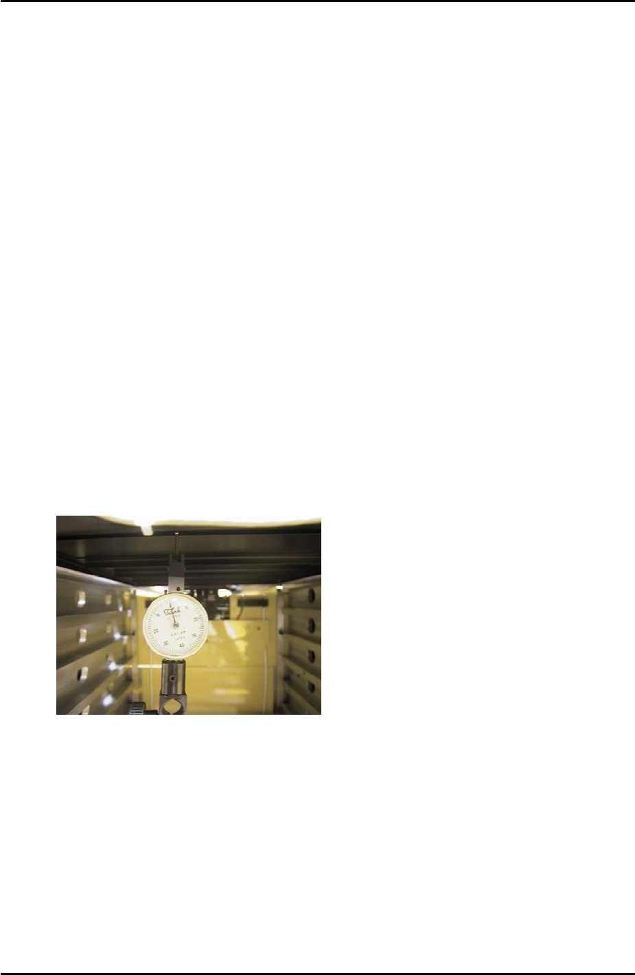
5. Set a dial gage to 0 on the tray pallet as shown in the photo:
6. Move the tray pallet forward by selecting [Manual Operation] – [Tray Operation] –
[Advance Shuttle].
7. Retract the tray pallet by selecting [Manual Operation] – [Tray Operation] – [Shuttle
Retract].
8. At this position the dial gage should read 0 +/- 0.1mm. If not adjust and lock the tray
catch stopper.
9. After adjusting the stopper so that the dial gage reads 0 +/- 0.1mm, advance and
retract the tray pallet again and confirm the dial gage reading is within tolerance.
Fuji Machine Mfg. Co., Ltd. Okazaki
SMT Equipment Quality Assurance Dept.
8 – 8 CS Section
FK-9F98-34 XP Series Type II Training Text for Service Engineers
Edition 2.0 XP242E – Chapter 8 Type II MTU Adjustment Page 9 of 18
8.12 Tray Catch Original Position Check Sensor Adjustment
1. Jog the U axis to the [U_ShuttleClampPos] + 3.43mm.
2. Loosen the sensor bracket and find the position that the sensor just comes ON, then lock
the sensor a further 0.5mm in the ON direction.
“TrayCatchOrgPo” Sensor
3. Confirm the sensor operation with I/O: X030 TrayCatchOrgPo.
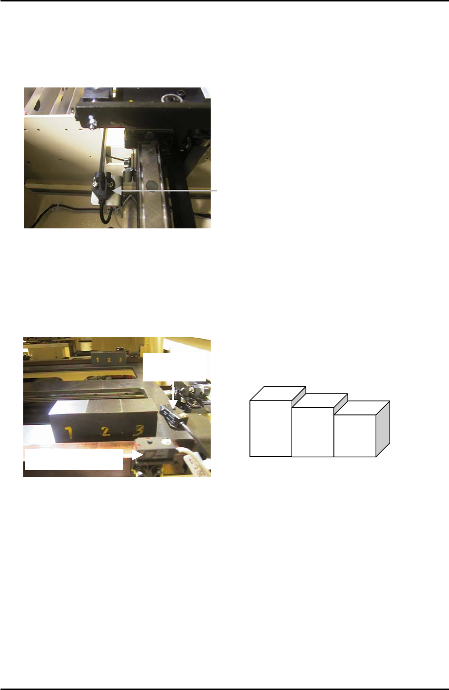
8.13 U-axis Interlock Sensor Adjustment
1. Put the tray pallet jig and two of the “three step jigs” in the U axis as shown below:
Interlock Sensor
Tray Height
check Sensor
“Three step jig” Z9631DEPJ3750
3
2
1
2. Adjust the height of the interlock sensor receiver and transmitter so that “X033
UaxisInter” is OFF when step 1 of the jig is in line with the sensor, and ON
when step 3 of
the jig is in line with the sensor.
Fuji Machine Mfg. Co., Ltd. Okazaki
SMT Equipment Quality Assurance Dept.
8 – 9 CS Section
FK-9F98-34 XP Series Type II Training Text for Service Engineers
Edition 2.0 XP242E – Chapter 8 Type II MTU Adjustment Page 10 of 18
8.14 Tray Height Check Sensor & [T_TrayEmptyOrg] Measurement
1. Put the tray pallet jig in slot [01,02] and bring it to the [T_TrayOrg] position.
2. Place two of the “three step” jigs on the tray pallet jig as shown below:
3. The path of the sensor beam is illustrated by the dotted line in the photo above.
4. Adjust the height of the “X03A TrayHeightChk1” sensor transmitter and receiver as
follows:
Jig Combination I/O
Status
Step 2 + 2 of the step jigs are in line with the sensor transmitter and receiver ON
Step 2 + 3 of the step jigs are in line with the sensor transmitter and receiver ON
Step 3 + 3 of the step jigs are in line with the sensor transmitter and receiver OFF
5. Repeat the adjustment for the “X03B TrayHeightChk2” sensor transmitter and receiver.
6. Remove the two “three step” jigs from the MTU, leaving only the tray pallet jig.
7. Slowly jog the T-axis up until both “X03A TrayHeightChk1” and “X03B TrayHeightChk2”
come ON. This position is “T_TrayEmptyOrg”. Select [Maintenance C] – [Proper Data
Editor] – [T_TrayEmptyOrg] – [Direct Servo Input] to save the current counter value in
proper data.
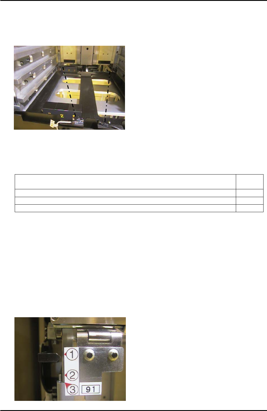
8.15 Tray Shutter Check Sensor Adjustment
1. Adjust the position of the sensor bracket so that when the tray shutter is at position 1 the
sensor LED is OFF, and comes ON when raising the shutter by 1mm.
X032 TrayShutOpnChk
Fuji Machine Mfg. Co., Ltd. Okazaki
SMT Equipment Quality Assurance Dept.
8 – 10 CS Section