XP Type II 工程师培训手册 (2.0).pdf.pdf - 第88页
FK-9F98-34 XP T ype II Series T raining T ext for Service Engineers Edition 2.0 XP142E – Chapter 6 Proper Dat a Measurement s Page 29 of 30 12. Set the conveyor wid th to minimum, then select [Manual Operation] – [Convey…
FK-9F98-34 XP Type II Series Training Text for Service Engineers
Edition 2.0 XP142E – Chapter 6 Proper Data Measurements Page 28 of 30
6.25 Conveyor Width Changer
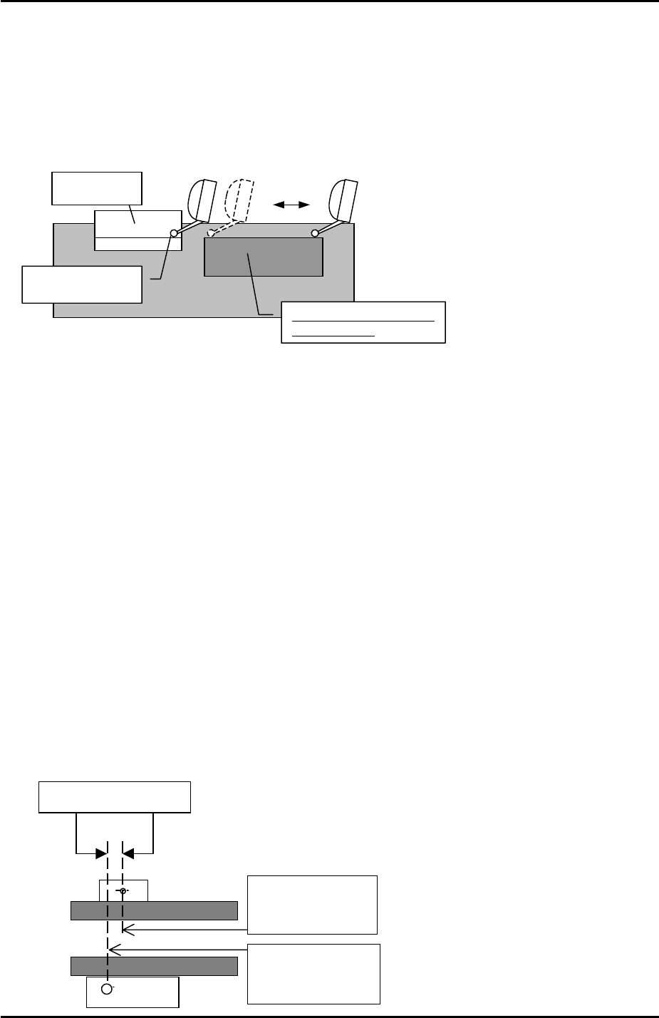
1. Equipment: lever type dial gage (0.01mm). Width defining mark bracket height
adjustment jig (A9531DEPJ1250).
2. Set the jig adjacent to the width defining mark bracket on the adjustable rail.
Flatness should be
within 0.05mm
Set the dial to “0”
Height jig
3. Set the dial gage to 0 on the reference side of the jig and slide it across the width defining
mark bracket.
4. Adjust the height of the bracket so that it is the same height as the jig (tolerance +/-
0.05mm). The flatness of the bracket should be within 0.05mm.
5. Set the conveyor width to approximately 100mm.
6. Select [Maintenance A] – [Jog] – [Fiducial] – and display the cross hairs on the screen.
7. Center the fiducial camera on the glass gage station fiducial mark and record the X-axis
counter value at this position.
8. Inch the fiducial camera in the Y direction until the width defining bracket comes into view,
then center the camera on the width defining mark.
9. Record the X-axis counter value at this position and subtract this figure from the X axis
counter value recorded in step 7. This value is the “ConvWidthMarkDiffX” proper data.
10. Select [Maintenance C] – [Proper data editor] – [Others] – [ConvWidthMarkDiffX] – and
manually input the figure calculated at step 9.
11. In the following example the ConvWidthMarkDiffX would be 1mm:
X-axis counter:
135.000 mm
ConvWidthMarkDiffX
X-axis counter:
136.000 mm
Fuji Machine Mfg. Co., Ltd. Okazaki
SMT Equipment Quality Assurance Dept.
6 – 28 CS Section

FK-9F98-34 XP Type II Series Training Text for Service Engineers
Edition 2.0 XP142E – Chapter 6 Proper Data Measurements Page 29 of 30
12. Set the conveyor width to minimum, then select [Manual Operation] – [Conveyor Width
adjustment] – [Measure Speed] – [START]. After the calibration is complete press [YES]
to save the results in proper data (ConvWidthMtrSpeed).
13. Once speed measurement is complete input a board width and select [Move] – [START].
The conveyor automatically moves to this board width.
14. Select a board with the same width as that input in step 13 and place it in the conveyor.
The board should fit smoothly into the conveyor, and there should be a clearance of
0.5mm between the conveyor and board. If not it is necessary to measure an offset.
15. Use the conveyor width changer inching tabs to change the conveyor width until the
clearance between board and conveyor is 0.5mm then select [Measure Offset] –
[START]. After the calibration is complete press [YES] to save the results in proper data
(ConvWidthOffset).
Fuji Machine Mfg. Co., Ltd. Okazaki
SMT Equipment Quality Assurance Dept.
6 – 29 CS Section

FK-9F98-34 XP Type II Series Training Text for Service Engineers
Edition 2.0 XP142E – Chapter 6 Proper Data Measurements Page 30 of 30
NOTES:
Fuji Machine Mfg. Co., Ltd. Okazaki
SMT Equipment Quality Assurance Dept.
6 – 30 CS Section