00197674-01-UM-E-Series-EN-12-2014.pdf - 第124页
3 Technical data and assemblies User manual SIPLACE E 3.5 Placement head From software version SC 708.0 12/2014 Editio n 124 3.5.3.1 Description The SIPLACE CP6 work s on the Collect&Plac e principle. The high- resol…
User manual SIPLACE E 3 Technical data and assemblies
From software version SC 708.0 12/2014 Edition 3.5 Placement head
123
3
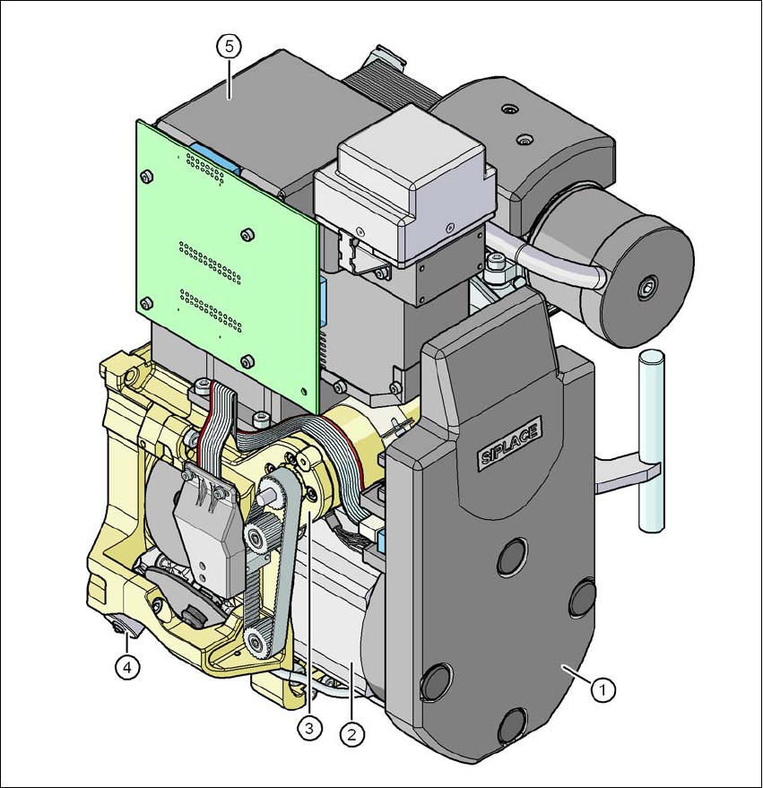
Fig. 3.5 - 6 SIPLACE CP6 - Function groups, part 2
3
(1) Intermediate distributor board, beneath the cover
(2) Star drive - DR motor
(3) Z axis motor
(4) Valve adjustment drive
(5) Component camera, type 30 GigE

3 Technical data and assemblies User manual SIPLACE E
3.5 Placement head From software version SC 708.0 12/2014 Edition
124
3.5.3.1 Description
The SIPLACE CP6 works on the Collect&Place principle. The high-resolution digital component
camera allows the SIPLACE CP6 to place components with an edge length of up to 27 mm accu-
rately and very quickly. It is therefore ideal for use with products containing a large proportion of
ICs. A considerable increase in output can be achieved even in the main application range from
PLCC 44 to QFP 208.
3.5.3.2 Sensor for the component reject bin
Item no. 03103405-xx Sensor for component reject bin
The sensor for the component reject bin monitors whether the reject bin is seated correctly in its
mount.
– If the reject bin was not inserted correctly, the machine cannot be started.
– If the reject bin jumps out of its mount during the placement process, the machine is stopped
immediately to avoid a head crash.
Each reject bin is monitored by a separate sensor.
3.5.3.3 Operation with a vacuum pump
The SIPLACE CP6 can be converted for operation with a vacuum pump for more efficient vacuum
generation (see Section 3.5.4
, page 126).
User manual SIPLACE E 3 Technical data and assemblies
From software version SC 708.0 12/2014 Edition 3.5 Placement head
125
3.5.3.4 Technical data
3
SIPLACE CP6
with component camera, type 30 GigE
Range of components
*a
*)a Please note that the component range that can be placed is also affected by the pad geometry, the cus-
tomer-specific standards and the packaging tolerances.
0201 to 27 x 27 mm²
Component specification
Max. height
Min. lead pitch
Min. lead width
Min. ball pitch
Min. ball diameter
Min. dimensions
Max. dimensions
Max. weight
8.5 mm
*b
0.3 mm
0.15 mm
0.25 mm for components< 18 x 18 mm²
0.35 mm for components ≥18 x 18 mm²
0.14 mm for components < 18 x 18 mm²
0.2 mm for components ≥ 18 x 18 mm²
0.6 x 0.3 mm²
27 x 27 mm²
5 g
*)b 19 mm if one nozzle is removed, With PP head configuration only
Nozzle types 38xx, 39xx
X/Y accuracy
*c
*)c The accuracy value was measured using the vendor-neutral IPC standard
± 52.5 μm/3σ, ± 70 μm/4σ
Angular accuracy ± 0.225°/3σ, ± 0.3°/4σ
Illumination levels 5
Possible illumination level setting
256
5