00197674-01-UM-E-Series-EN-12-2014.pdf - 第158页
3 Technical data and assemblies User manual SIPLACE E 3.10 Changeover table for SIPLACE E From software version SC 708.0 12/2014 Edition 158 3.10.4 F iducial on t he changeover table 3 Fig. 3.10 - 4 Fiducials on the chan…
User manual SIPLACE E 3 Technical data and assemblies
From software version SC 708.0 12/2014 Edition 3.10 Changeover table for SIPLACE E
157
3
3.10.2 Description
The tape reel container holds tape reels up to a size of 17" (432 mm).
There are two 5 mm wide gaps on the left and right, between the tape container and the change-
over table, for holding setup lists.
The pullout waste tape container can be found beneath the chassis. The cut waste tape travel
down a chute into the waste tape container, which must be emptied as it fills up.
3
3.10.3 Technical Data
3
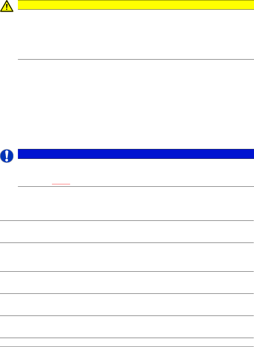
CAUTION
Risk of breaking handles!
Risk of breaking handles when transporting the changeover table.
When transporting the changeover table, do not lift it by its handles.
Only use the handles to push the changeover table.
Use a fork-lift if you want to transport the changeover table or lift it off the pallet.
PLEASE NOTE
All changeover tables must be docked onto the machine in order to operate it.
Fill any free locations with dummy feeder modules as described in
section 2.7.5.1
, page 86.
Changeover table dimensions
Changeover table with 60 tracks (length x width) 735 mm x 820 mm
Height (PCB transport height)
Standard
Option
900 mm to 930 mm
950 mm
Weight of changeover table with 60 tracks
Without feeder modules
With feeder modules (fully configured)
88 kg
138 kg
Tape reel diameter
Standard up to 432 mm (17“)
Feeder locations
Changeover table with 60 tracks 60 feeders with SIPLACE
SmartFeeder 8 mm E
Changeover table changeover time < 1 minute
3 Technical data and assemblies User manual SIPLACE E
3.10 Changeover table for SIPLACE E From software version SC 708.0 12/2014 Edition
158
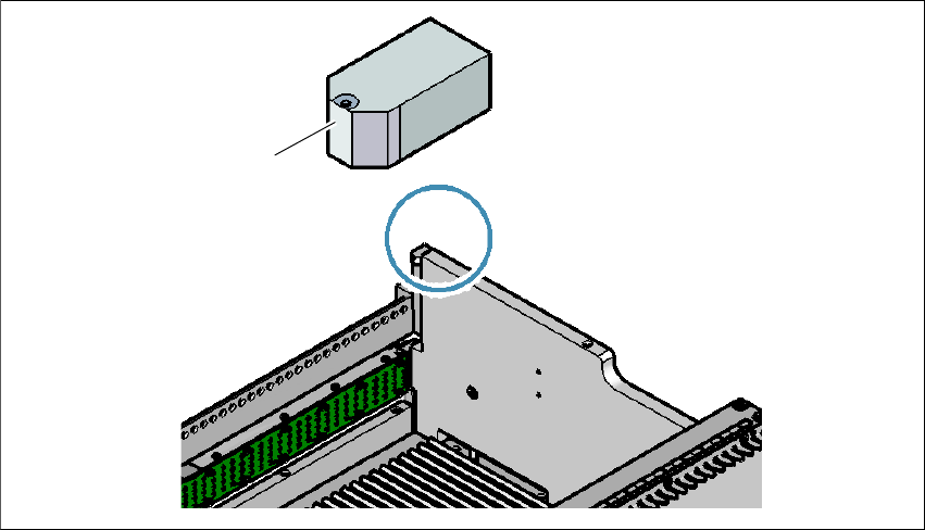
3.10.4 Fiducial on the changeover table
3
Fig. 3.10 - 4 Fiducials on the changeover table
(1) Fiducial on the changeover table
Once the SIPLACE changeover table has been docked in, the machine measures the fiducial on
the changeover table.
For components with an edge length of less than 0.5 mm, i.e. 0402 components and smaller, the
position of the component is determined with the tape pocket before the first component is picked
up.
(1)
User manual SIPLACE E 3 Technical data and assemblies
From software version SC 708.0 12/2014 Edition 3.10 Changeover table for SIPLACE E
159
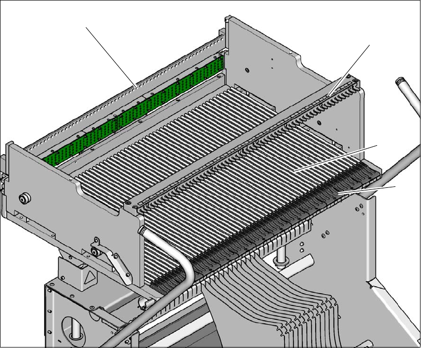
3.10.5 Changeover table for SIPLACE E
The front slider guides of the feeder modules are placed on the insertion aid. As it is pushed in,
the guides of the feeder module slide on the guide profile as far as the stop bar. A centering hole
on the stop bar holds the "front" centering pin of the SIPLACE SmartFeeder E. At the same time,
the locking latch of the changeover table latches onto the locking roller of the feeder module. The
"back" centering pin on the top of the feeder module is held by the recess in the centering bar.
3
Fig. 3.10 - 5 Changeover table, back view
(1) Insertion aid
(2) Guide profile
(3) Locking bar to guide and lock the SIPLACE SmartFeeder E in place
(4) Centering bar
(1)
(2)
(3)
(4)