00197674-01-UM-E-Series-EN-12-2014.pdf - 第227页
User manual SIPLACE E 5 Working with the machine From software version SC 708.0 12/2014 Edition 5.10 Carrying out a sight check 227 5.10.3 Checking t he support pins Check the position of t he suppo rt pins on the lift…

5 Working with the machine User manual SIPLACE E
5.10 Carrying out a sight check From software version SC 708.0 12/2014 Edition
226
5
Check the multicolor status display.
– If it lights up green, the feeder module is on standby.
– If it lights up orange, it is signaling a warning. The LEDs shine accordingly.
– If the status display lights up red, a malfunction has occurred. The LEDs shine accord-
ingly.
A list of the LED and status displays on the SmartFeeder operator panel is given in sec-
tion 5.12.1
, page 239. 5
If the status display is off, the cause may be as follows: 5
– The feeder module is not in the current setup.
– The feeder module is defective.
– The feeder module has been disabled (due to a drop in pressure, for example)
5.10.2 Splicing the tapes in good time
5
5
CAUTION
Problems with cover foil withdrawal!
If the cover foil tears, this could lead to problems with the cover foil withdrawal.
There is an integral blade (item 2) for easily cutting the on the 8 and 12 mm SIPLACE
SmartFeeder E.
PLEASE NOTE
Late splicing of tapes
Late splicing of tapes can lead to prolonged down times.
Splice the tapes early enough so that the feeder modules do not run out of compo-
nents.
PLEASE NOTE
Early splicing of tapes
Early splicing of tapes can have the following consequence: when the old tape is rolled up
onto the new reel, the new reel could become too full and the tape will slide off it and get
caught up. This will again result in pick-up errors and prolonged down times.
Splice the tapes at the right time so that the old and new tapes do not get caught.
User manual SIPLACE E 5 Working with the machine
From software version SC 708.0 12/2014 Edition 5.10 Carrying out a sight check
227
5.10.3 Checking the support pins
Check the position of the support pins on the lifting table:
– Make sure that the support pins do not collide with components on the underside of the
PCBs.
– In addition, make sure that the support pins do not collide with the PCB conveyor panels.
5 Working with the machine User manual SIPLACE E
5.10 Carrying out a sight check From software version SC 708.0 12/2014 Edition
228
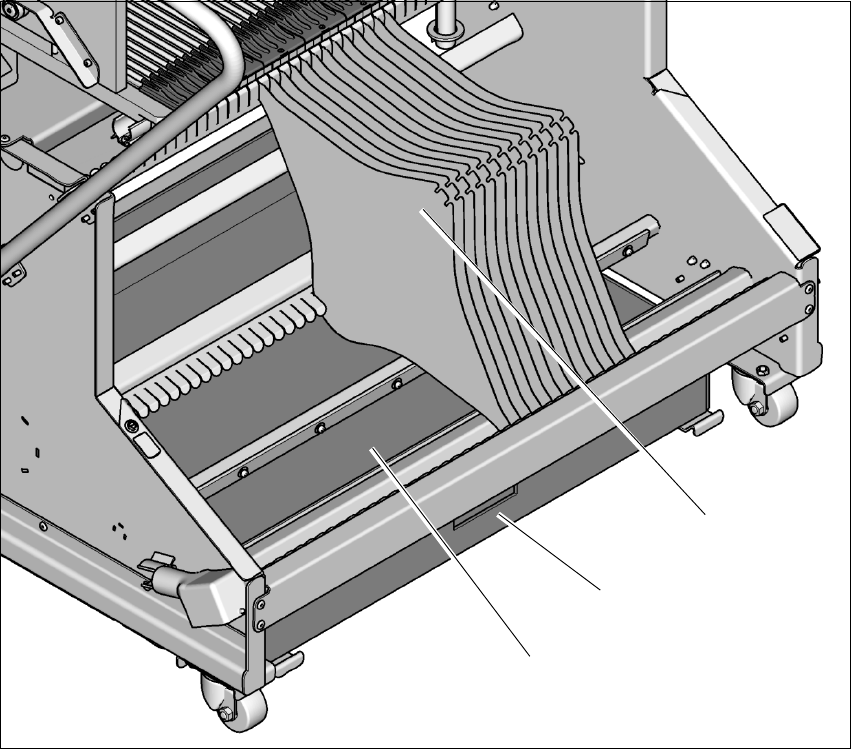
5.10.4 Inserting separating plates into the tape container
The separating plate has different edges and can be inserted into the tape container in two
ways. If spindles are used, the recesses for the spindles in the separating plate point up-
wards. If you do not use spindles, the
rounded
edge of the separating plate points up.
Insert the separating plates as shown in fig. 5.10 - 2 and remember that the smallest division
of the tape container is a 2x division. This will help avoid placement errors.
Check that the separating plates engage in the same positions on the three guide rails. Oth-
erwise the separating plate will be offset or bent.
5
Fig. 5.10 - 2 Separating plates in the tape container
(1) Waste tape container
(2) Tape container
(3) Separating plates
(1)
(3)
(2)