00197674-01-UM-E-Series-EN-12-2014.pdf - 第229页
User manual SIPLACE E 5 Working with the machine From software version SC 708.0 12/2014 Edition 5.11 Setting up t he feeder modules 229 5.11 Setting up the feeder modules 5.11.1 Notes on handling fe eder modules Feeder m…
5 Working with the machine User manual SIPLACE E
5.10 Carrying out a sight check From software version SC 708.0 12/2014 Edition
228
5.10.4 Inserting separating plates into the tape container
The separating plate has different edges and can be inserted into the tape container in two
ways. If spindles are used, the recesses for the spindles in the separating plate point up-
wards. If you do not use spindles, the
rounded
edge of the separating plate points up.
Insert the separating plates as shown in fig. 5.10 - 2 and remember that the smallest division
of the tape container is a 2x division. This will help avoid placement errors.
Check that the separating plates engage in the same positions on the three guide rails. Oth-
erwise the separating plate will be offset or bent.
5
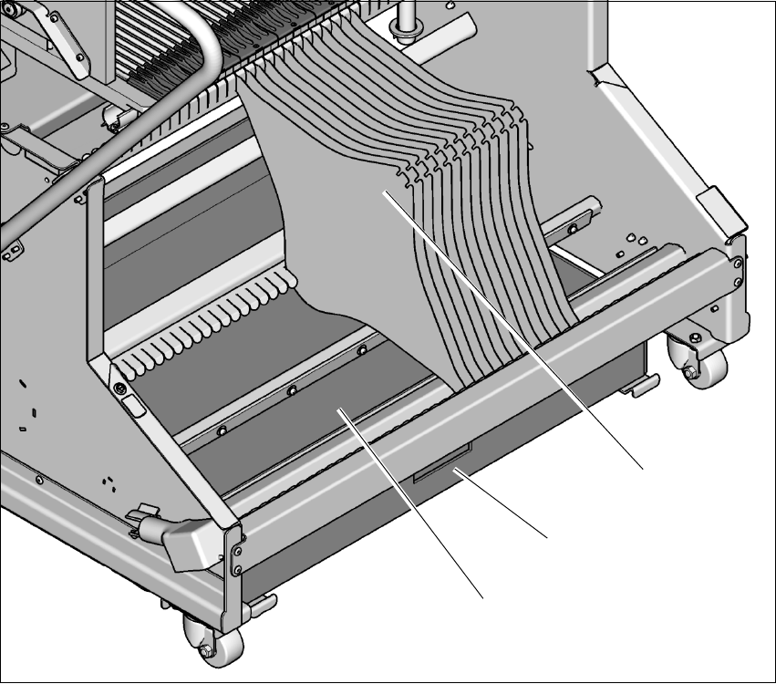
Fig. 5.10 - 2 Separating plates in the tape container
(1) Waste tape container
(2) Tape container
(3) Separating plates
(1)
(3)
(2)
User manual SIPLACE E 5 Working with the machine
From software version SC 708.0 12/2014 Edition 5.11 Setting up the feeder modules
229
5.11 Setting up the feeder modules
5.11.1 Notes on handling feeder modules
Feeder modules are precision devices. You should therefore handle the feeder modules with care.
Avoid bumping feeder modules into obstacles.
Do not drop the feeder modules.
Always use suitable tools for cleaning and checking.
5.11.2 Removing SIPLACE SmartFeeder E from the changeover table
5
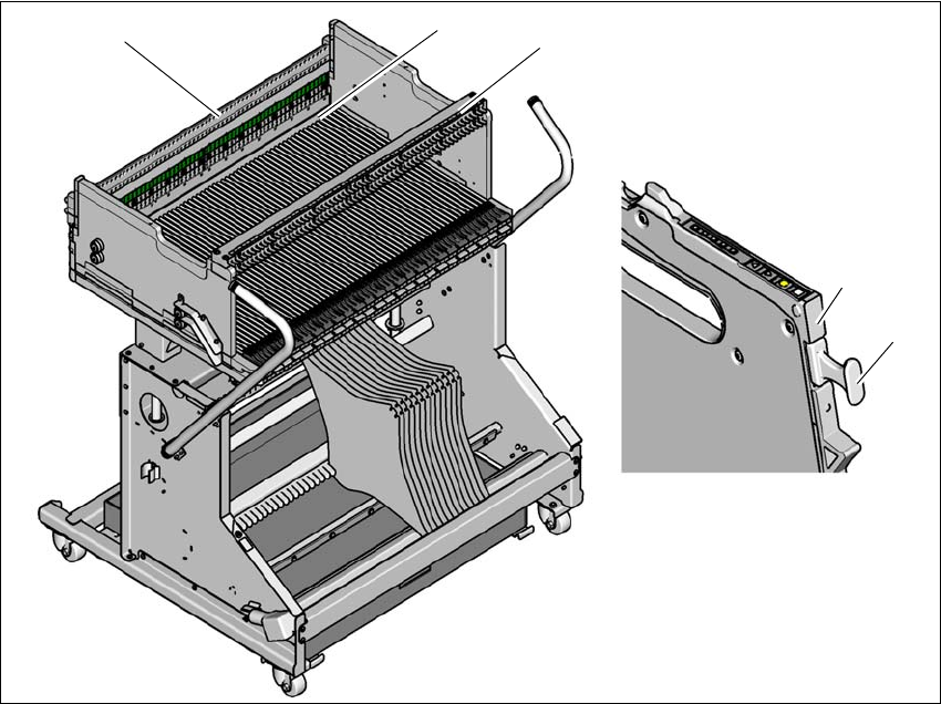
Fig. 5.11 - 1 Removing SIPLACE SmartFeeder E from the changeover table
(1) Removal handle
(2) Status display
(3) Feeder locking bar
(4) Stop bar
(5) Centering bar
(1)
(2)
(5)
(4)
(3)
5 Working with the machine User manual SIPLACE E
5.11 Setting up the feeder modules From software version SC 708.0 12/2014 Edition
230
On standby, the status display (item 2) lights up green if the feeder module is contained in the cur-
rent setup. If the feeder module is not contained in the current setup, the status display remains
off.
The SIPLACE SmartFeeder E is locked in position in the changeover table by a latch. The proce-
dure for removing feeder modules from the changeover table is as follows:
Pull the removal handle (item 1). The status display goes red and then the status display
goes out.
Use the removal handle to pull the feeder module out of the locking bar (item 3) and stop
bar (item 4).
Remove the feeder module. Pay attention to the centering bar (item 5).