00197674-01-UM-E-Series-EN-12-2014.pdf - 第278页
6 Station extensions User manual SIPLACE E 6.1 Nozzle changer From software version SC 708.0 12/2014 Editio n 278 6.1.4.3 Position of nozzle changer for the SIPLACE CP6 6 Fig. 6.1 - 18 Position of nozzle cha nger for the…

User manual SIPLACE E 6 Station extensions
From software version SC 708.0 12/2014 Edition 6.1 Nozzle changer
277
6.1.4.2 Technical data
6
Nozzle changer for the SIPLACE CP6
Number of nozzle holders
38xx
39xx
24
48
Number of nozzle magazines 4
Nozzle types 38xx/39xx
Nozzle changeover time Approx. 2s per nozzle
Compressed air connection 0.45 MPa (4.5 bar)
6 Station extensions User manual SIPLACE E
6.1 Nozzle changer From software version SC 708.0 12/2014 Edition
278
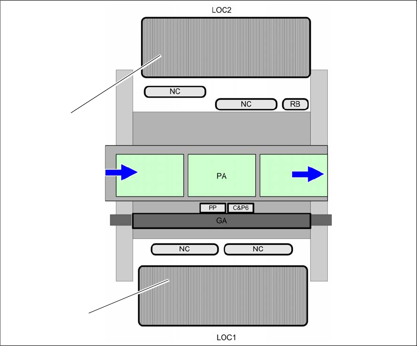
6.1.4.3 Position of nozzle changer for the SIPLACE CP6
6
Fig. 6.1 - 18 Position of nozzle changer for the SIPLACE CP6 - example
(1) Changeover table on location 1
(2) Changeover table on location 2
(NC) Nozzle changer
(RB) Reject bin
(PA) Placement area
(GA) Gantry
(2)
(1)
User manual SIPLACE E 6 Station extensions
From software version SC 708.0 12/2014 Edition 6.1 Nozzle changer
279
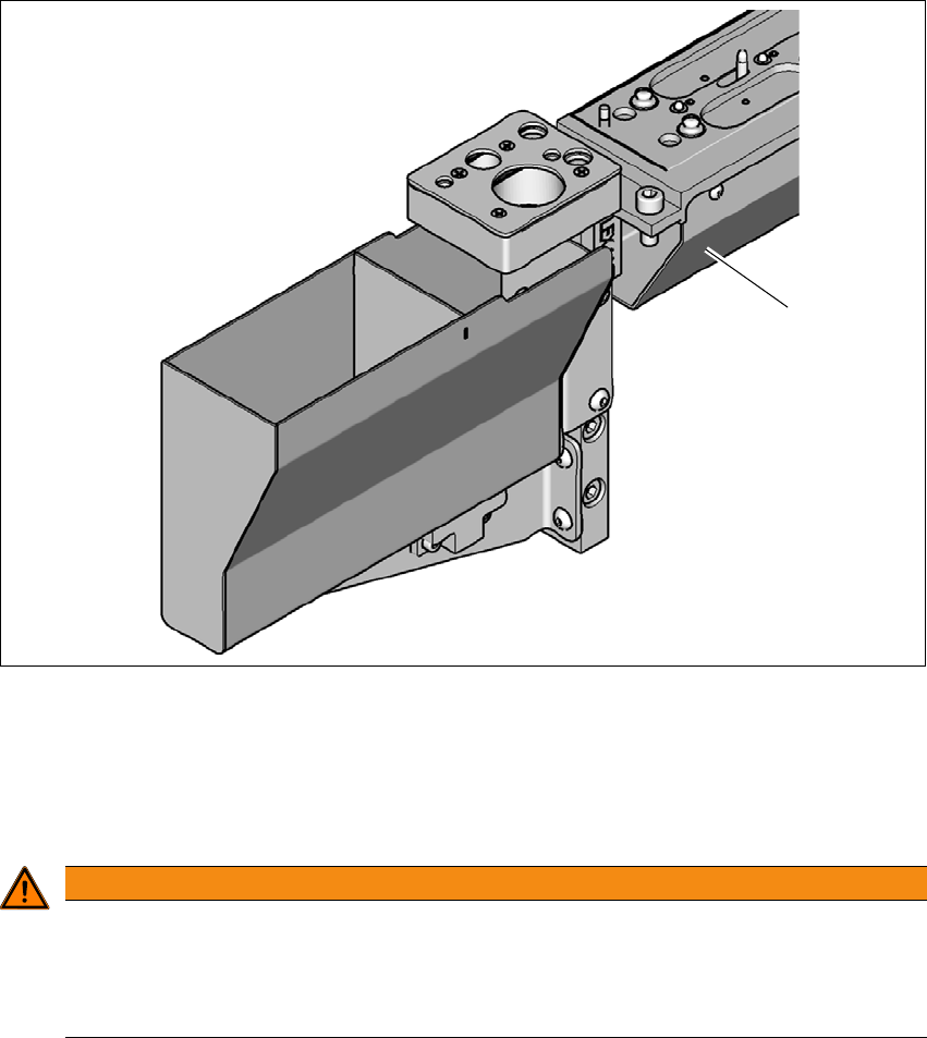
6.1.4.4 Assembly
In SIPLACE E machines, the nozzle changers are installed on the machine frame.
6
Fig. 6.1 - 19 Assembly position
(1) Sloping side points towards the changeover table COT insert
Align the nozzle changer so that the sloping side points towards the changeover table COT
insert.
6
WARNING
Risk of head crashes with mixed configurations!
There is a risk of head crashes with mixed configurations.
Only install the associated nozzle changer for each placement head, with the nozzle
magazines for the respective placement head.
(1)