00197674-01-UM-E-Series-EN-12-2014.pdf - 第82页
2 Operational safety User manual SIPLACE E 2.7 Safety features From software version SC 708.0 12/2014 Editi on 82 2.7.2.2 Position of protective switches on the machine 2 Fig. 2.7 - 4 Position of protective switches on t…

User manual SIPLACE E 2 Operational safety
From software version SC 708.0 12/2014 Edition 2.7 Safety features
81
EMERGENCY STOP button (item 4 in fig. 2.7 - 3, page 79 and item 3 in fig. 2.7 - 2, page 78) 2
The EMERGENCY STOP button is red and latches in the ON position when pressed. When you
press the EMERGENCY STOP button, the switching contact of the EMERGENCY STOP circuit
opens and the safety contactors trips. The link voltage (300 VDC) for the gantry axes and the link
voltage (160 VDC) for the star axes is switched off. The servo amplifiers for the DP and Z axes
are still supplied with 42 VDC. The signaling contact of the EMERGENCY STOP button opens
and the message "EMERGENCY STOP pressed" appears on the screen. The following modules
are deactivated:
– PCB conveyor
– PCB clamping
– Width adjustment
– PCB stopper
– Feeder Control Unit
– Safety valve for the tape cutter
–Star axis
–Gantry axis
2
2
PLEASE NOTE
Placement is interrupted and can then either be continued or canceled once the machine
is working correctly again.
2 Operational safety User manual SIPLACE E
2.7 Safety features From software version SC 708.0 12/2014 Edition
82
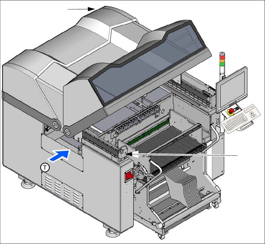
2.7.2.2 Position of protective switches on the machine
2
Fig. 2.7 - 4 Position of protective switches on the machine
(1) Protective cover switch, location 1
(2) Protective cover switch, location 2
Protective cover switch 1 and 2 (item 1 and 2 in fig. 2.7 - 4, page 82) 2
These switches check whether the protective covers are closed. When they are closed, the
EMERGENCY STOP contact and the signaling contact are closed. After pressing the Start button
the covers are locked.
(1)
(2)
User manual SIPLACE E 2 Operational safety
From software version SC 708.0 12/2014 Edition 2.7 Safety features
83
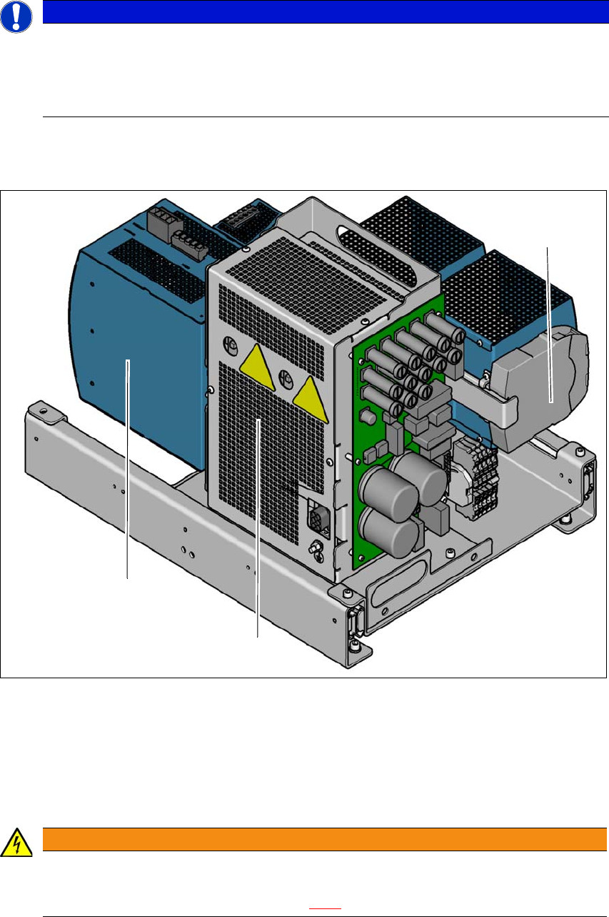
2.7.3 Safety contactors
2
Fig. 2.7 - 5 Overview of the safety contactors
2
(1) Safety unit (behind cover)
(2) Capacitor module
(3) Safety relay
2
PLEASE NOTE
The protective covers are electrically and mechanically locked
During operation, the protective covers are locked and cannot be opened.
Press the stop button. The protective covers can be opened.
See also Section 2.5 on page 69.
WARNING
Safety instructions about lethal voltages!
Always follow the safety instructions concerning potentially lethal voltages - even when
the machine is switched off. (See section 2.8.1
from page 88).
(1)
(2)
(3)