CX200-4(Maint).pdf - 第278页
4.3.4 Nozzle Recognition Errors AA BB C DDDDD Detail Code Secondary Error Classification (1 to 3) Primary Error Classification (0) Classification (04) of Recognition Functions (a) Error IDs “*” will be filled with detail…
(2) Manipulate the trackball until the actual fiducial mark and the tem-
plate of the fiducial mark (located at the center of the crosshair)
overlap each other.
Note: Enlarge the view for accurate alignment operation. Other-
wise, components may not be placed accurately.
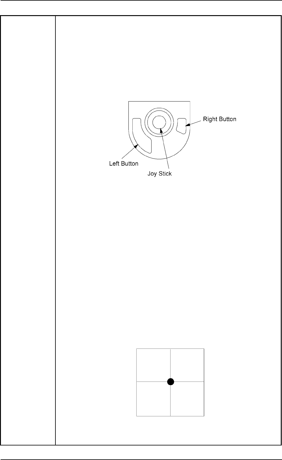
How to manipulate the trackball
• Move the actual fiducial mark with the trackball.
• Use the right button to enlarge the view.
• Use the left button to reduce the view.
Fig. 4B25
(3) After adjusting the actual fiducial mark and the template accurately,
press the right and left buttons of the at the same time.
The “AUTO OPN.” window resumes.
When the [START] button is pressed, the automatic operation starts
again.
Note: Pressing both right and left buttons at the same time is vali-
dated only once.
If the actual fiducial mark and the template are not adjusted
correctly, components may not be placed accurately. In this
case, follow the remedial operation described below.
(3-1) Press the [STOP] button to stop the machine.
(3-2) Press the [Cancel] button to interrupt the automatic opera-
tion.
(3-3) Perform the zeroing operation on all axes.
(3-4) Open the “Run Mode” tab sheet. (Operation Sequence: [OPN.
MODE] Button Æ “Run Mode” Tab Sheet) Press the [SEMI-
AUTO (STEP)] button to re-start the automatic operation.
Fig. 4B26 Sample Display of Recognition Window
at Completion of Alignment Operation
01 10-003 2-188 AFO01ETRP
4.3 Recognition Error IDs and Remedial Procedures
4.3.4 Nozzle Recognition Errors
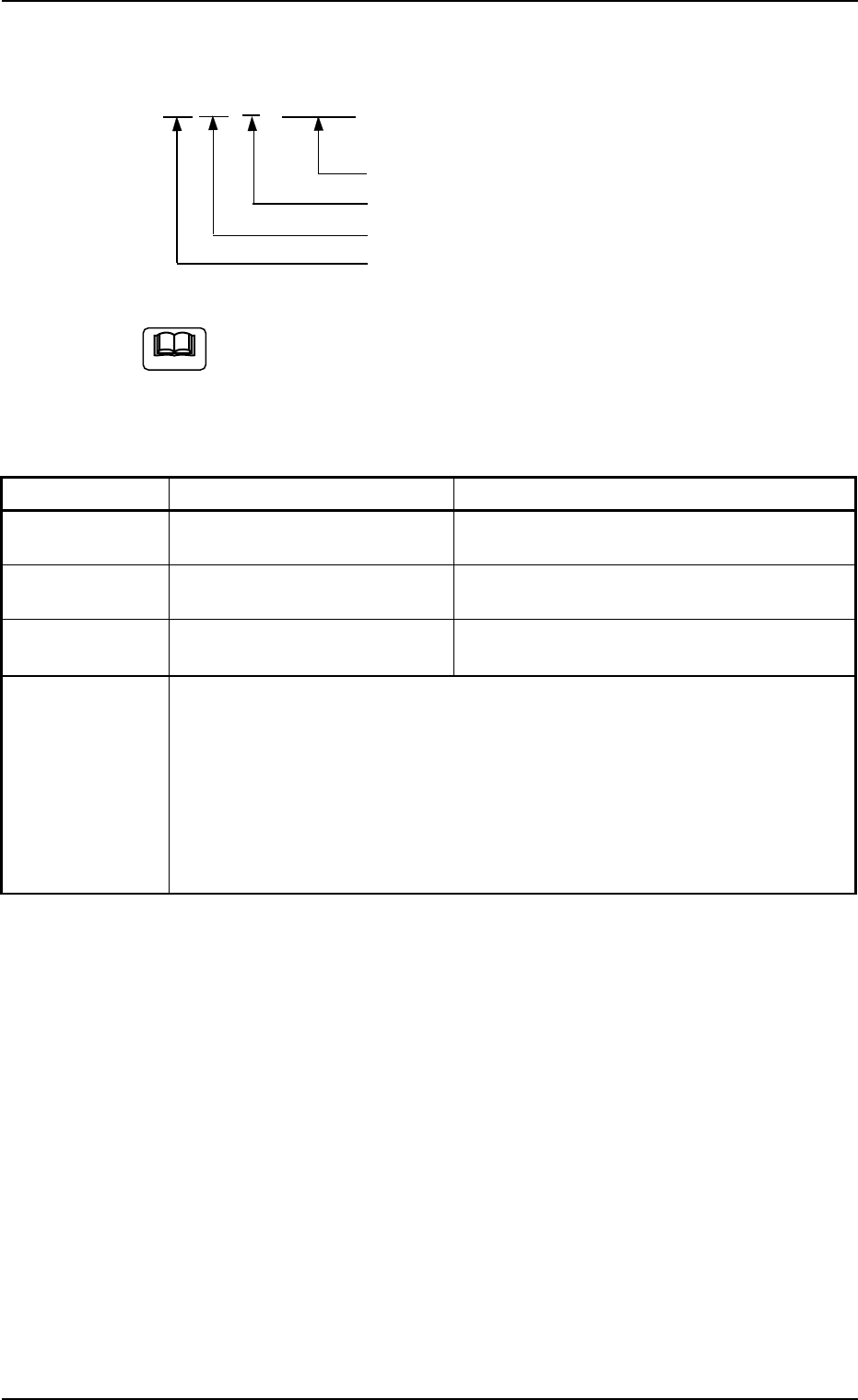
AA BB C DDDDD
Detail Code
Secondary Error Classification (1 to 3)
Primary Error Classification (0)
Classification (04) of Recognition Functions
(a) Error IDs “*” will be filled with detail codes.
(b) When an error ID other than the described ones is issued,
contact our service personnel for some advice.
Table 4B13
Recognition Error ID Item Description
04 00 1 ***** ---- Nozzle Not Detected.
04 00 2 ***** ---- Nozzle size has exceeded the allowable range.
04 00 3 ***** ---- Nozzle position has exceeded the allowable range.
(Cause 1) The nozzle is attached abnormally.
(Cause 2) The nozzle type data is abnormal.
(Remedy 1) Attach the nozzle correctly.
(Remedy 2) Check the nozzle type data. If necessary, correct it.
01 10-003 2-189 AFO01ETRP
Note
4.3 Recognition Error IDs and Remedial Procedures
4.3.5 Various Teach Errors
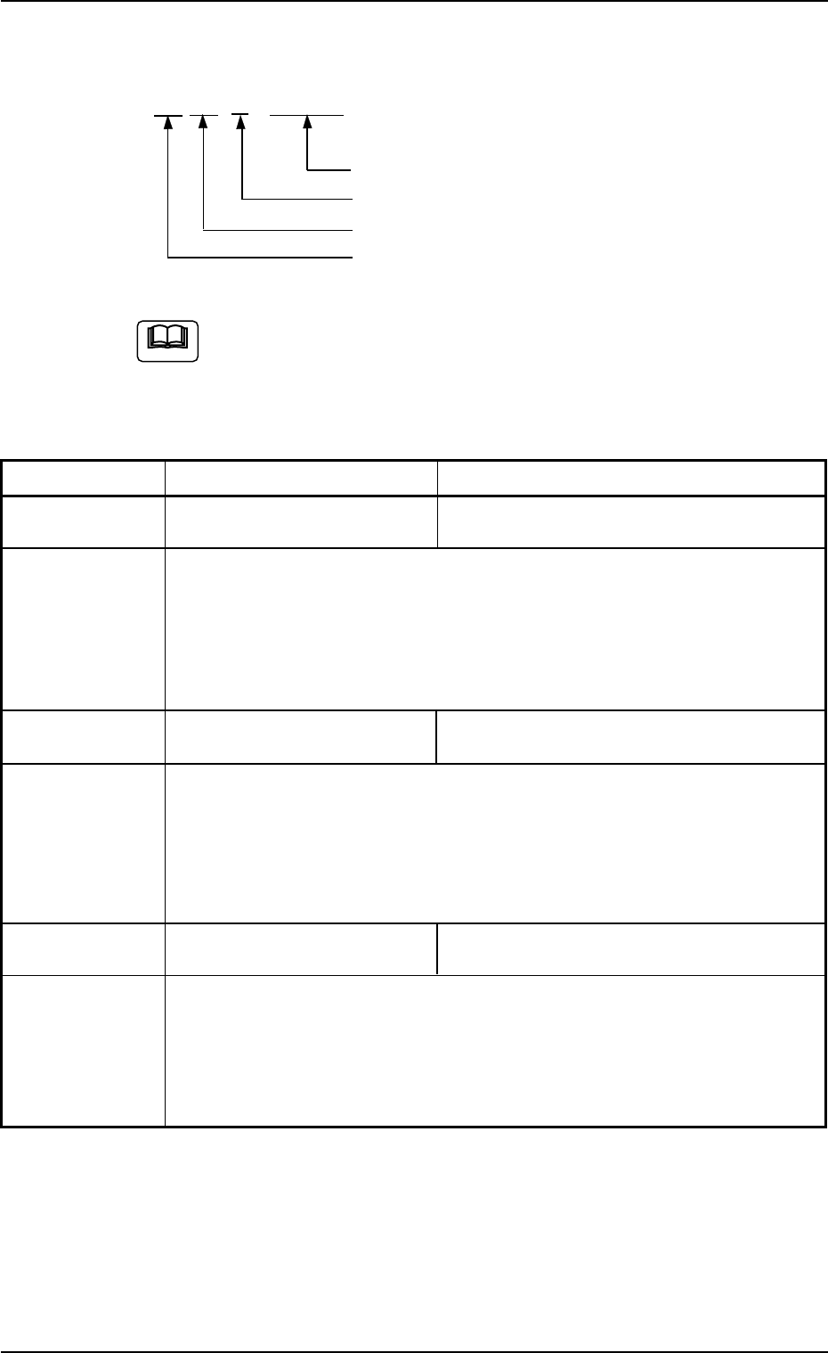
AA BB C DDDDD
Detail Code
Secondary Error Classification (0)
Primary Error Classification (0 to 5)
Classification (10) of Recognition Functions
(a) Error IDs “*” will be filled with detail codes.
(b) When an error ID other than the described ones is issued,
contact our service personnel for some advice.
Table 4B14
Recognition Error ID Item Description
10 01 0 ***** ---- Failed in Detection of Camera Position during
Camera Offset Teaching Operation.
(Cause 1) Set the jig correctly.
(Remedy 1) Set the jig correctly.
Or, contact our service personnel for some advice.
10 02 0 11001 ---- Error in Camera Sensitivity Check Operation
The brightness is not suitable for the adjustment.
(Cause 1) The camera sensitivity may be abnormal.
(Remedy 1) Contact our service personnel for details.
10 03 0 11001 ---- Error in Lighting Intensity Data (Back Lighting)
The data has exceeded the specified range.
(Cause 1) The longevity of the lamp might have ended.
(Remedy 1) Replace the lamp with a new one.
Or, contact our service personnel for some advice.
01 10-003 2-190 AFO01ETRP
Note
4.3 Recognition Error IDs and Remedial Procedures