CX200-4(Maint).pdf - 第63页
(2) Attachment of V acuum Nozzle • Before attaching a vacuum nozzle, check that the end of the nozzle is not damaged, the tapered section is unscratched, the pick-up hole unclogged, and the grip section undeformed. • Sel…
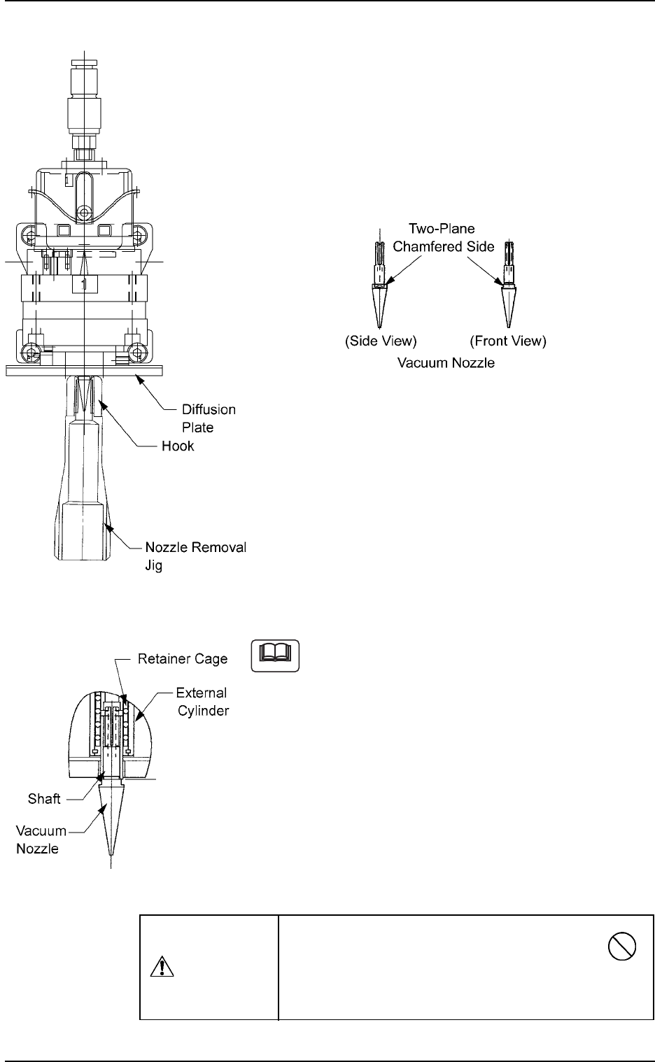
(1-6) Detachment of Vacuum Nozzle
Push the bottom of the nozzle removal jig gently and set it on the vacuum
nozzle such that the hook is engaged correctly with the two-plane cham-
fered side of the vacuum nozzle.
Note: The nozzle removal jig cannot be used for nozzle type 031 (φ6
nozzle). Detach the nozzle by hand.
Fig. 4A65
(1-7) Pull down the nozzle removal jig to detach the vacuum nozzle.
(a) Do not score the diffusion plate while detaching
a vacuum nozzle.
(b) A miniature stroke bearing is used at the
nozzle up/down movement section which
consists of the shaft, the retainer cage, and the
external cylinder units.
When the section is disassembled by mistake,
be sure to correctly reassemble each unit
which belongs to the section.
When the nozzle is detached, the miniature
stroke bearing and the shaft section should not
be removed.
Fig. 4A64-2
Note
Avoid getting the removed vacuum nozzle
magnetized.
When the nozzle is magnetized, an error will occur
in component pick-up or placement.
CAUTION
Fig. 4A66
1.4 Maintenance Method
0110-003 1-51 AFO01ETRP
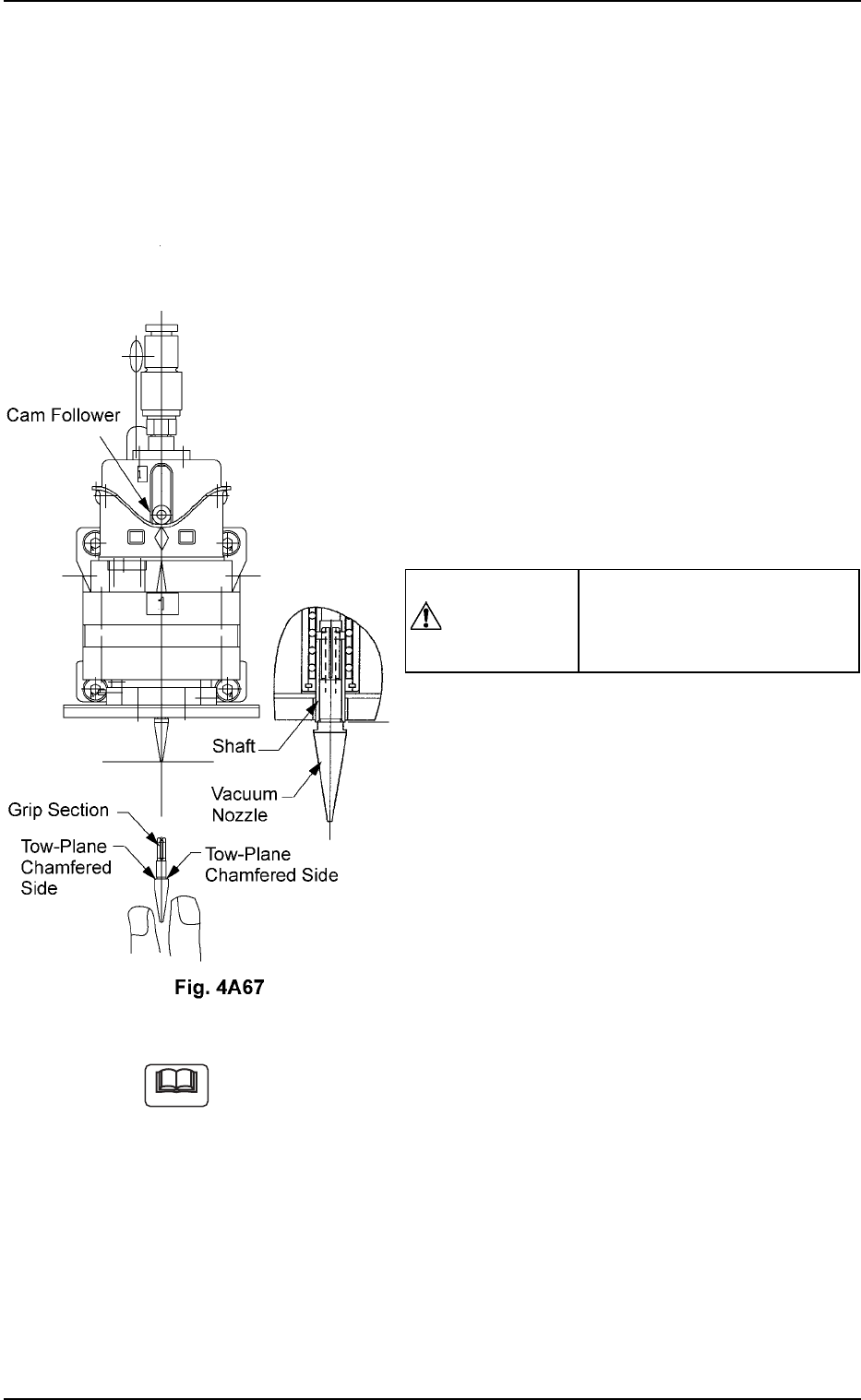
(2) Attachment of Vacuum Nozzle
• Before attaching a vacuum nozzle, check that the end of the nozzle
is not damaged, the tapered section is unscratched, the pick-up hole
unclogged, and the grip section undeformed.
• Select the nozzle which meets the parameters specified in the place-
ment head nozzle data.
(2-1) Move the center shaft of the nozzle posi-
tion No. to be attached toward the front side
of the machine.
(2-2) While holding the cam follower with your
finger, orient the two-plane chamfered side
horizontally and insert the vacuum nozzle
over the shaft until it stops.
(2-3) Set the [OPERATION] switch to the “RUN”
side.
(2-4) Use the “Head/Nozzle” tab in the “TEACH-
ING” window (submenu) and perform a
teaching operation on the nozzle.
Do not scratch the diffusion plate while attaching a vacuum nozzle.
CAUTION
Inserting a nozzle forcibly
over the shaft in wrong direc-
tion deforms the grip section.
Note
1.4 Maintenance Method
0110-003 1-52 AFO01ETRP
0110-003 1-53 AFO01ETRP
1.4 Maintenance Method
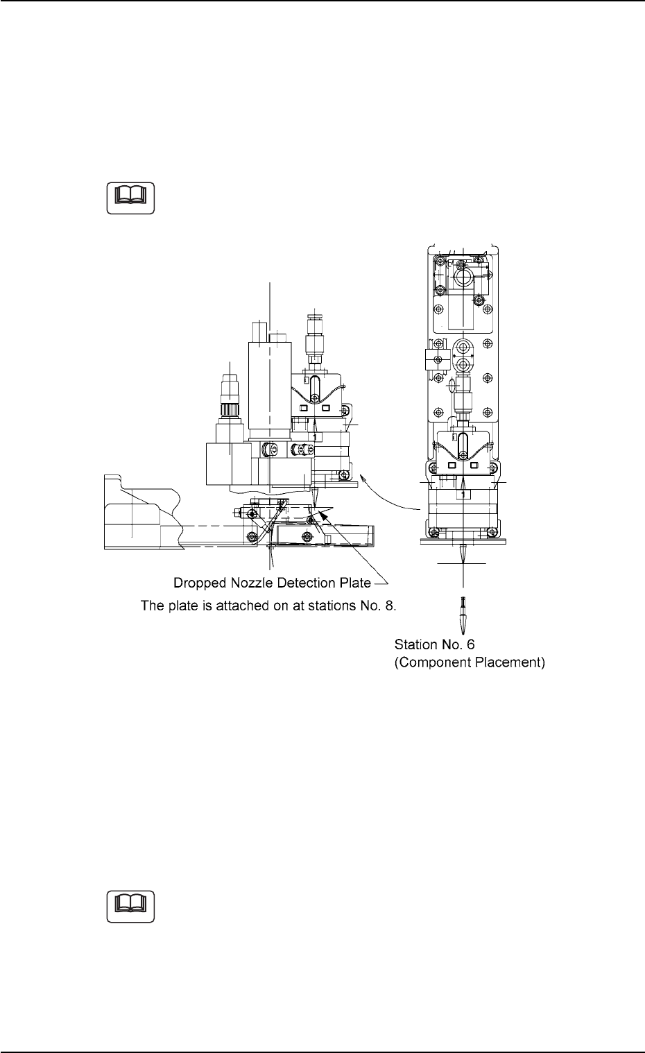
(3) Checking of Attached Vacuum Nozzle
• After the vacuum nozzle is attached, rotate the rotary turret with the
cam hand-rotating wheel to let the nozzle pass over the dropped nozzle
detection plate. Check that the end of the nozzle does not touch the
plate. If it touches the plate, re-attach the vacuum nozzle.
The vacuum nozzle should be set in the descending mode
when it passes over the dropped nozzle detection plate.
Fig. 4A68
(4) Nozzle Offset Teaching
Refer to “5.4 “Head/Nozzle” Tab” in “Section 6” of “Volume 2: Opera-
tion (Supervisor)” for details and perform teaching operations.
Wipe off dirt and dust on the end of a nozzle which was detected as
defective through teaching operation and then re-perform the teaching
operation.
Refer to “5.4 “Head/Nozzle” Tab” in “Section 6” of “Volume 2:
Operation (Supervisor)” for the items to be checked when a
nozzle is detected as a defective one through teaching opera-
tion.
When the machine operation is started with a defective
nozzle (detected by teaching operation) attached, the nozzle
is bypassed and not used.
Note
Note