CX200-4(Maint).pdf - 第71页
(3) Attachment of Holder to Head (3-1) Apply “DAPHNE EPONEX GREASE No. 1” thinly to the bearing guide section of the holder and the pin end. (3-2) Match the holder guide with the cutout of the head’s center shaft and ins…
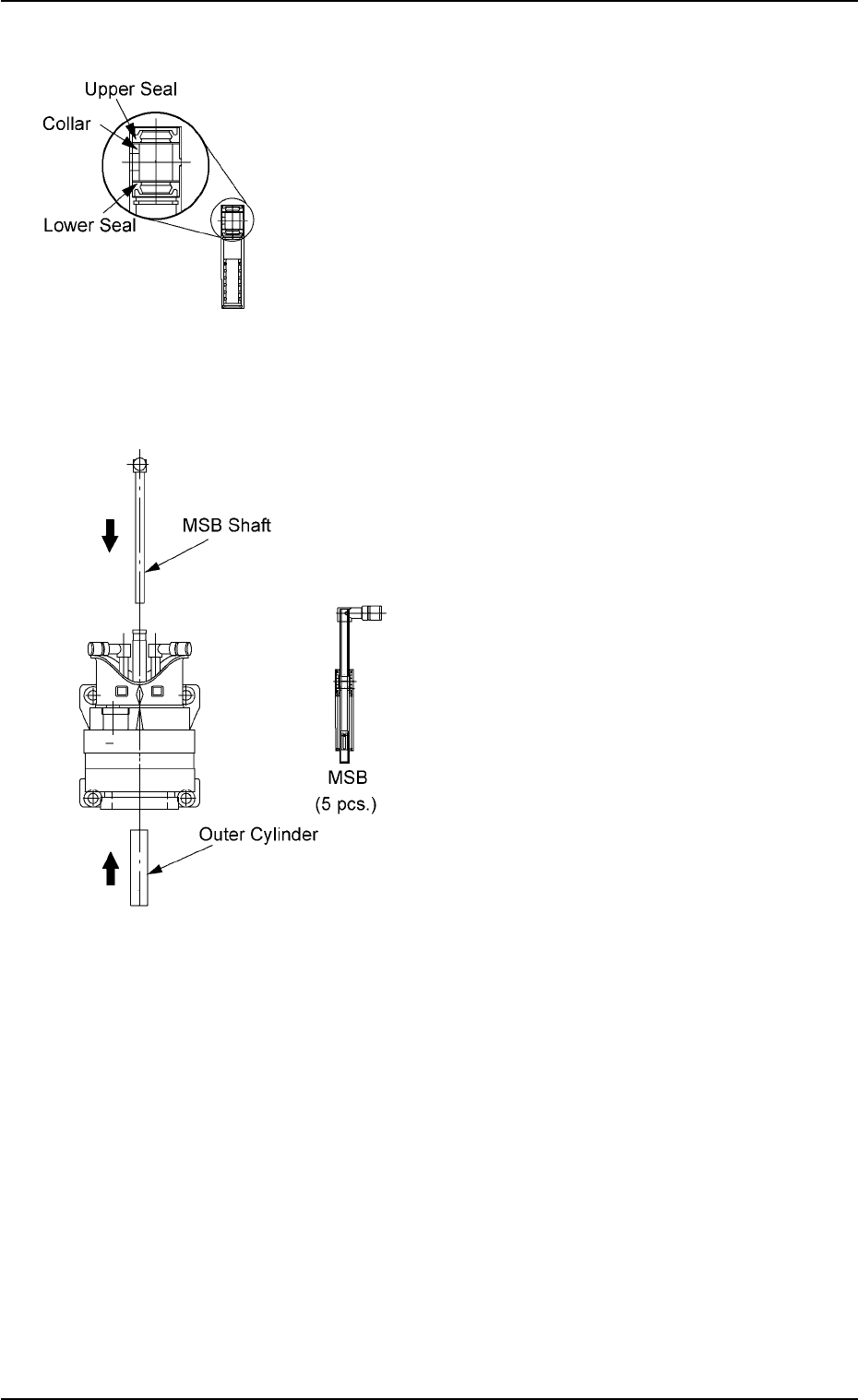
• Attachment of Miniature Stroke Bearing
(1) Attachment of Seals and Collar to Outer
Cylinder of Miniature Stroke Bearing
(1-1) Wipe the seals with a dry cloth and apply
“DAPHNE EPONEX GREASE No. 1” to
the internal side of the seals.
(1-2) Attach the lower seal, the collar, and the
upper seal to the outer cylinder in this
order.
Note: Be sure to attach the seals and the
collar in the correct directions.
(2) Attachment of Miniature Stroke Bearing to
Head
(2-1) Insert the outer cylinder of the miniature
stroke bearing from under the head.
Note: Adjust the outer cylinder such that the
cutout faces inward.
(2-2) Insert the shaft from the top of the head
with the MSB inserting jig being attached.
(2-3) Detach the MSB inserting jig.
Note: If the jig is slippery, wipe it with a cloth
soaked in industrial alcohol.
(2-4) Attach the anchor plate to the outer cylin-
der and secure it with the screw (M3L10).
Apply “Screw Lock (1401B)” to the screw
and tighten it with a tightening torque of 7
kgfcm.
01 10-003 1-59
AFO01ETRP
Fig. 4A79
Fig. 4A80
1.4 Maintenance Method
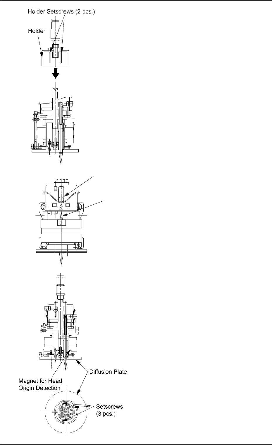
(3) Attachment of Holder to Head
(3-1) Apply “DAPHNE EPONEX GREASE No.
1” thinly to the bearing guide section of the
holder and the pin end.
(3-2) Match the holder guide with the cutout of
the head’s center shaft and insert the
holder into the top of the head.
(3-3) Push the holder into the shaft until it stops
and match the marker of the cam unit
with the center of the cam follower.
(3-4) Apply “Screw Lock (1401B)” to the set-
screws. After that, tighten the setscrews
with a tightening torque of 5 kgfcm.
(4) Attach the diffusion plate to the head and
secure it with three setscrews.
Note: There are two types of setscrews -
“Special Ones (Anti-Loosening Pro-
cessed Ones)” and “Normal Ones”.
Tighten the special setscrews with a
tightening torque of 10 kgfcm.
When the normal setscrews are used,
apply “Screw Lock (1401B)” to them and
tighten with a tightening torque of 5
kgfcm.
(5) Apply “DAPHNE EPONEX GREASE No. 1”
thinly to the cam face of the holder.
Fig. 4A81
Fig. 4A82
01 10-003 1-60
AFO01ETRP
1.4 Maintenance Method
Cam Follower
Marker of Cam Unit
Fig. 4A81-1

(6) Attachment of Head Assembly to Head
Assembly Holder
(6-1) Fit the pilot pin hole on the rear side of the
head assembly into the pilot pin on the
holder side.
(6-2) Fasten the head assembly with two
“M4X12” setscrews and two “M4X16”
setscrews.
(Tightening Torque: Approx. 44 kgfcm)
(6-3) Insert the hose.
Note: Do not apply a wrench, etc., to the
magnet for head origin detection. Other-
wise, the magnet will be demagnetized.
If the magnet is demagnetized, the origin
may not be detected.
(7) Perform the “Head Origin” and the “Head/
Nozzle” teaching operations on the attached
nozzle.
Note: Refer to “5.4” and “5.5” in “Section 6” of
“Vol. 2: Operation (Supervisor)” for the
offset teaching operations.
• The head origin offset must be ±3
degrees or less.
• The head center offset must be ±3
mm.
01 10-003 1-61
AFO01ETRP
1.4 Maintenance Method