CX200-4(Maint).pdf - 第72页
(6) Attachment of Head Assembly to Head Assembly Holder (6-1) Fit the pilot pin hole on the rear side of the head assembly into the pilot pin on the holder side. (6-2) Fasten the head assembly with two “M4X12” setscrews …
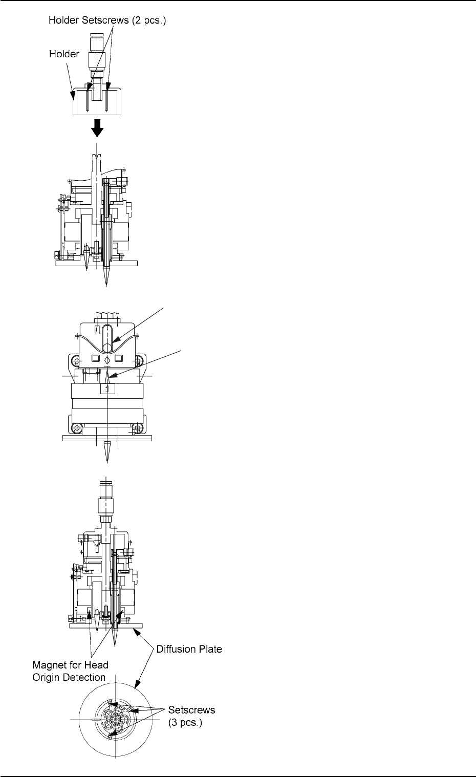
(3) Attachment of Holder to Head
(3-1) Apply “DAPHNE EPONEX GREASE No.
1” thinly to the bearing guide section of the
holder and the pin end.
(3-2) Match the holder guide with the cutout of
the head’s center shaft and insert the
holder into the top of the head.
(3-3) Push the holder into the shaft until it stops
and match the marker of the cam unit
with the center of the cam follower.
(3-4) Apply “Screw Lock (1401B)” to the set-
screws. After that, tighten the setscrews
with a tightening torque of 5 kgfcm.
(4) Attach the diffusion plate to the head and
secure it with three setscrews.
Note: There are two types of setscrews -
“Special Ones (Anti-Loosening Pro-
cessed Ones)” and “Normal Ones”.
Tighten the special setscrews with a
tightening torque of 10 kgfcm.
When the normal setscrews are used,
apply “Screw Lock (1401B)” to them and
tighten with a tightening torque of 5
kgfcm.
(5) Apply “DAPHNE EPONEX GREASE No. 1”
thinly to the cam face of the holder.
Fig. 4A81
Fig. 4A82
01 10-003 1-60
AFO01ETRP
1.4 Maintenance Method
Cam Follower
Marker of Cam Unit
Fig. 4A81-1

(6) Attachment of Head Assembly to Head
Assembly Holder
(6-1) Fit the pilot pin hole on the rear side of the
head assembly into the pilot pin on the
holder side.
(6-2) Fasten the head assembly with two
“M4X12” setscrews and two “M4X16”
setscrews.
(Tightening Torque: Approx. 44 kgfcm)
(6-3) Insert the hose.
Note: Do not apply a wrench, etc., to the
magnet for head origin detection. Other-
wise, the magnet will be demagnetized.
If the magnet is demagnetized, the origin
may not be detected.
(7) Perform the “Head Origin” and the “Head/
Nozzle” teaching operations on the attached
nozzle.
Note: Refer to “5.4” and “5.5” in “Section 6” of
“Vol. 2: Operation (Supervisor)” for the
offset teaching operations.
• The head origin offset must be ±3
degrees or less.
• The head center offset must be ±3
mm.
01 10-003 1-61
AFO01ETRP
1.4 Maintenance Method
1.4.6 Lamp Replacement of Light Source Device for Recognition
Lighting
(1) Light Source Devices
Light Source Devices : MHF-D100LRSO-2
MHF-D100LRSC-2
Lamp : LM-100
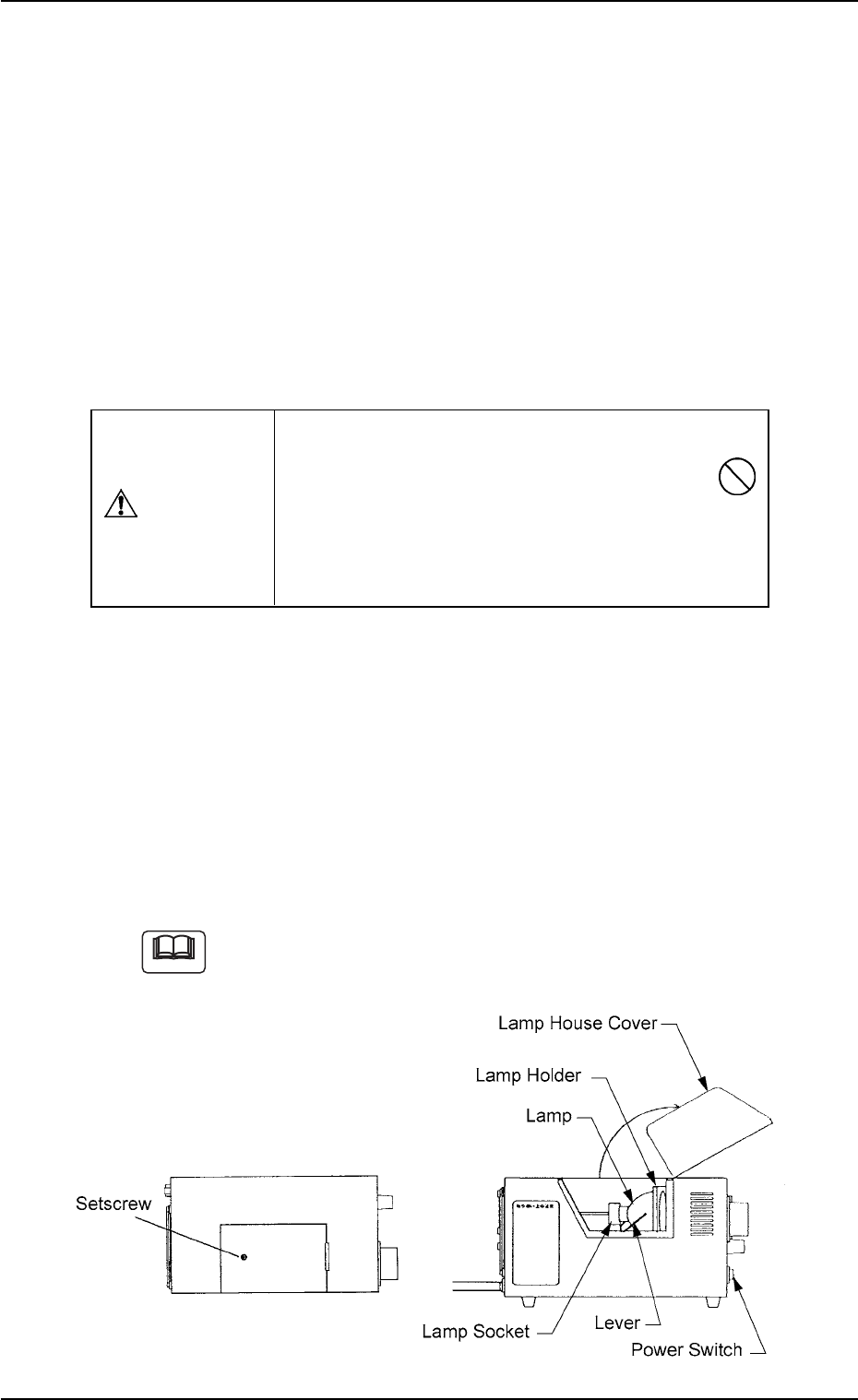
(2) Lamp Replacement Procedure
• Turn off the power switch of the light source device and check that
the LED (Orange) of the power switch extinguishes.
• Loosen the setscrew on the main body of the light source device and
open the lamp house cover.
• Lift the lever located on the left side of the lamp in the arrow direction.
The lamp will also be lifted up.
• Pull out the lamp straight up from the lamp holder.
• Detach the lamp from the socket.
When the lamp is inserted or pulled out, be sure not to forcibly
screw the terminal into or unscrew it from the socket. Other-
wise, the socket may be damaged.
Fig. 4A83
Do not touch the lamp right after it has been turned
off because it is very hot. Wait for about 3 to 5
minutes or until it cools down.
Be sure to wear gloves made of thick material (for
example, cotton work gloves) to replace the lamp
right after it has been turned off.
CAUTION
Note
0110-003 1-62 AFO01ETRP
1.4 Maintenance Method