00193364-04.pdf - 第18页
2 Assembly instructions Splice Detection Table Cont roller SIPLACE HS-50 Splice Detection Table Controller 09/2008 Edition 18 2.5 Prep aration : Familiarize yourself with the new hardware components, as shown in Fig. 2.1…
Splice Detection Table Controller 2 Assembly instructions Splice Detection Table Controller SIPLACE HS-50
09/2008 Edition
17
2.3 Tools and Auxiliary Equipment
– Metric Hex Ball End Wrench Set (also called “Allen” Wrench)
– Diagonal cutters
– #1 Cross Point Screwdriver (also called a “Phillips Head” screwdriver)
– a small flat bladed screwdriver.
2.4 Parts
Contents HS50 Splice Detection table controller package
(item no.: 00119032-01) 2
Number Description item no.:
- 1 table controller unit (TC) 00366007-xx
- 1 cable to the machine 03047976-xx
- 1 adapter power supply 00368490-xx
- installation material
2 Assembly instructions Splice Detection Table Controller SIPLACE HS-50 Splice Detection Table Controller
09/2008 Edition
18
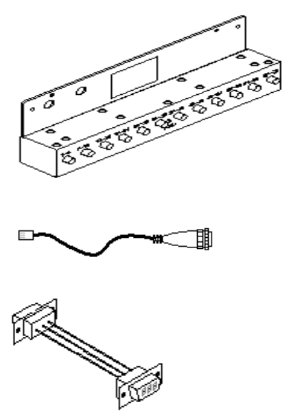
2.5 Preparation
: Familiarize yourself with the new hardware components, as shown in Fig. 2.10 - 1.
2
Abb. 2.10 - 1 Retrofitting kit: splice detection for HS changeover table
2
Table controller HS-50 (TC)
Cable to the machine
Adapter for power supply
Splice Detection Table Controller 2 Assembly instructions Splice Detection Table Controller SIPLACE HS-50
09/2008 Edition
19
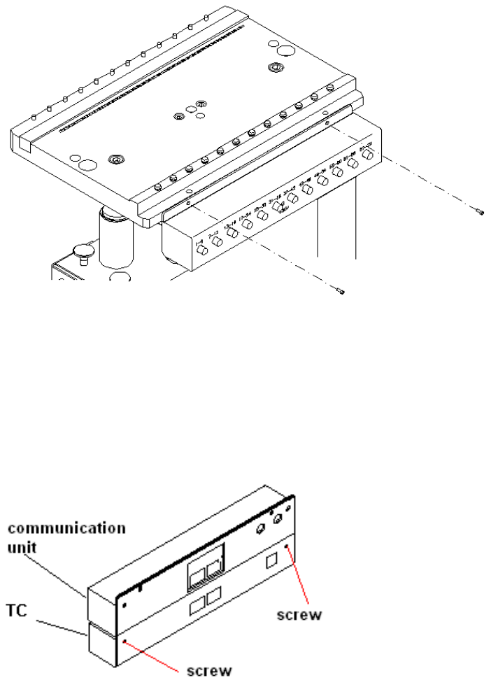
2.6 Installation
: Remove the communication unit. Loosen the screws that fix the unit to the changeover table
(Fig. 12 - 1), and remove the power supply and communication plugs on the back.
2
Abb. 2.10 - 1 changeover table with a communication unit
: Then connect the communication unit and table controller (TC). Any screws protruding from
the communication unit should fit into the recesses in the table controller case. If necessary,
loosen the screws on the back of the table controller slightly (Fig. 12 - 2), adjust the communi-
cation unit and tighten the screws once more.
2
Abb. 2.10 - 2 Connected communication unit and table controller (TC))
2