00193364-04.pdf - 第20页
2 Assembly instructions Splice Detection Table Cont roller SIPLACE HS-50 Splice Detection Table Controller 09/2008 Edition 20 : Reconnect any plugs th at you removed when you dismantled the communication un it . : Remove…
Splice Detection Table Controller 2 Assembly instructions Splice Detection Table Controller SIPLACE HS-50
09/2008 Edition
19
2.6 Installation
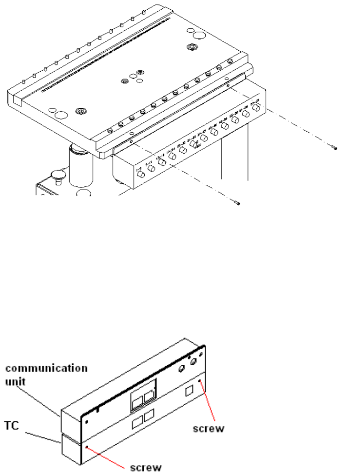
: Remove the communication unit. Loosen the screws that fix the unit to the changeover table
(Fig. 12 - 1), and remove the power supply and communication plugs on the back.
2
Abb. 2.10 - 1 changeover table with a communication unit
: Then connect the communication unit and table controller (TC). Any screws protruding from
the communication unit should fit into the recesses in the table controller case. If necessary,
loosen the screws on the back of the table controller slightly (Fig. 12 - 2), adjust the communi-
cation unit and tighten the screws once more.
2
Abb. 2.10 - 2 Connected communication unit and table controller (TC))
2
2 Assembly instructions Splice Detection Table Controller SIPLACE HS-50 Splice Detection Table Controller
09/2008 Edition
20
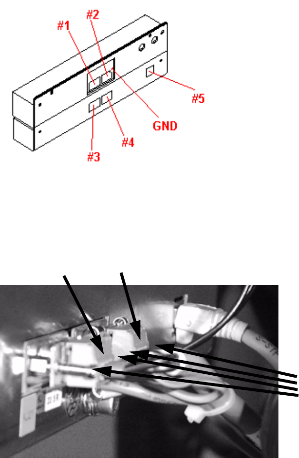
: Reconnect any plugs that you removed when you dismantled the communication unit .
: Remove the body of plug #3.
: Connect the communication plug (9-pin) to socket #1and power supply plug (3-pin) to socket
#3. Fix the green/yellow ground cable to the back.
2
Abb. 2.10 - 3 Complete unit showing the connector pin and ground assignments
: If there is a body on plug #4, remove it.
: Sockets #2 and #4 are connected using the cable supplied (Fig. 12 - 3).
2
: Then place the complete unit on the bed of the changeover table once more.
: Plug the CAT5 cable (03047976-xx) into the connector #5.
Now fix the CAT5 cable at the bottom of the TC casing using the clamps.
Run the cable outwards to the left or right side depending on the changeover table.
4 screws
plug #3
plug #4
Splice Detection Table Controller 2 Assembly instructions Splice Detection Table Controller SIPLACE HS-50
09/2008 Edition
21
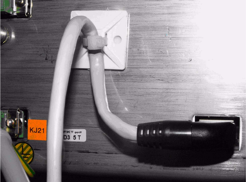
2.6.1 Cable layout
: Mind that the cables are long enough to fix them safely or bind them with others..
2
: Stick the gluey socket as showm in the figure and fix the cable 03047976-xx with cable tie.
2
2
2
2
2
2
2
2
2
2
2