00193364-04.pdf - 第21页
Splice Detection Table Controller 2 A ssembly instructi ons Splice Detection Table Controller SIPLACE HS-50 09/2008 Edition 21 2.6.1 Cable layout : Mind that the cables are long eno ugh to fix them safely or bind them wi…
2 Assembly instructions Splice Detection Table Controller SIPLACE HS-50 Splice Detection Table Controller
09/2008 Edition
20
: Reconnect any plugs that you removed when you dismantled the communication unit .
: Remove the body of plug #3.
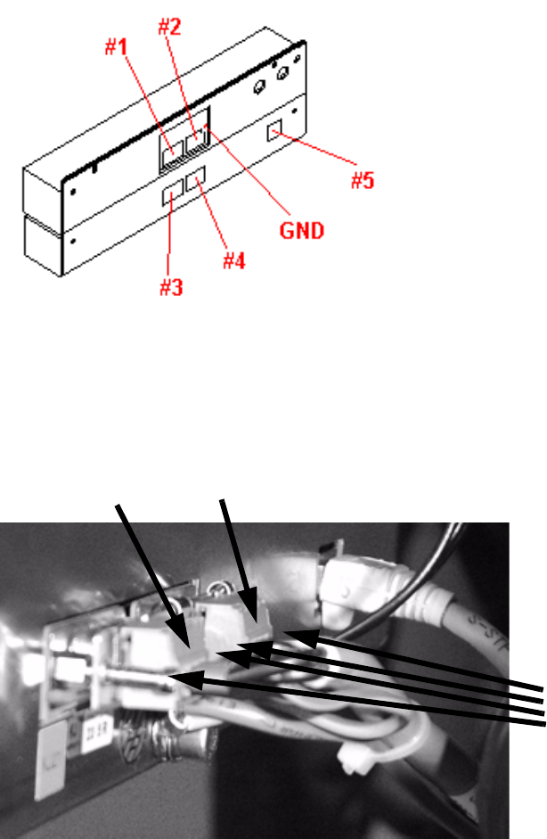
: Connect the communication plug (9-pin) to socket #1and power supply plug (3-pin) to socket
#3. Fix the green/yellow ground cable to the back.
2
Abb. 2.10 - 3 Complete unit showing the connector pin and ground assignments
: If there is a body on plug #4, remove it.
: Sockets #2 and #4 are connected using the cable supplied (Fig. 12 - 3).
2
: Then place the complete unit on the bed of the changeover table once more.
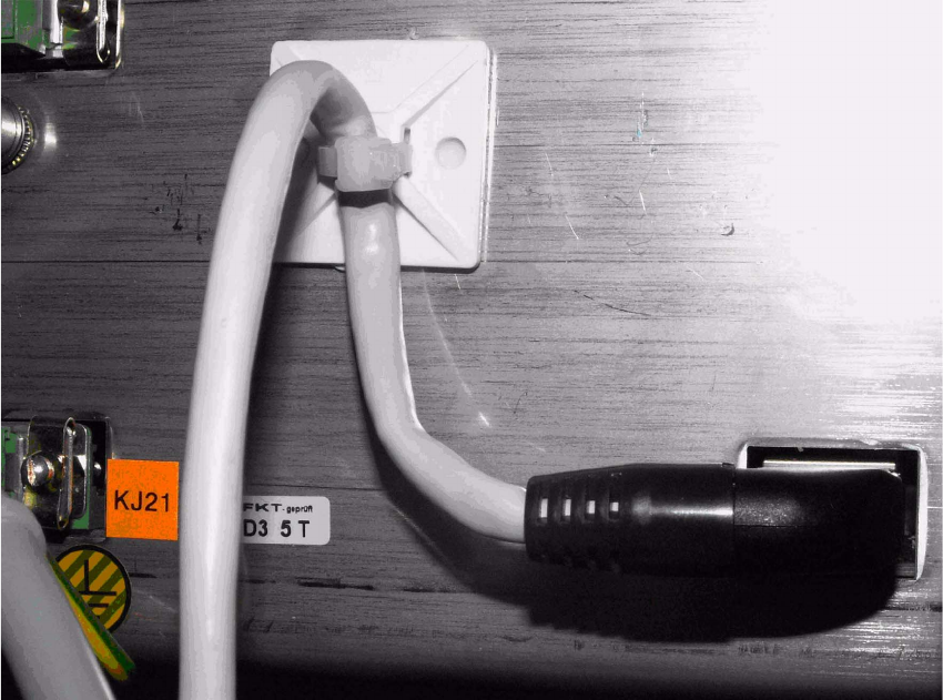
: Plug the CAT5 cable (03047976-xx) into the connector #5.
Now fix the CAT5 cable at the bottom of the TC casing using the clamps.
Run the cable outwards to the left or right side depending on the changeover table.
4 screws
plug #3
plug #4
Splice Detection Table Controller 2 Assembly instructions Splice Detection Table Controller SIPLACE HS-50
09/2008 Edition
21
2.6.1 Cable layout
: Mind that the cables are long enough to fix them safely or bind them with others..
2
: Stick the gluey socket as showm in the figure and fix the cable 03047976-xx with cable tie.
2
2
2
2
2
2
2
2
2
2
2
2 Assembly instructions Splice Detection Table Controller SIPLACE HS-50 Splice Detection Table Controller
09/2008 Edition
22
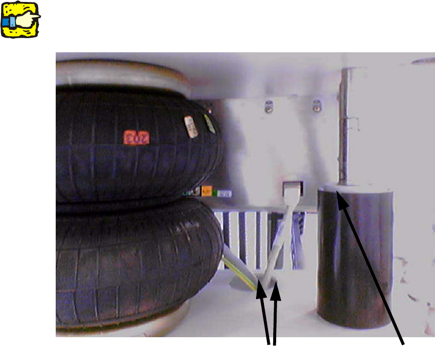
: Bind the cable with a cable to the power supply cable.
2
Avoid clamping the cable loop at lowered component table between guide pillar and guide bush.2
2
2
2
2
2
2
2
2
2
2
2
2
Bind the cables
don’t clamp the
cable loop