46230811.pdf - 第13页
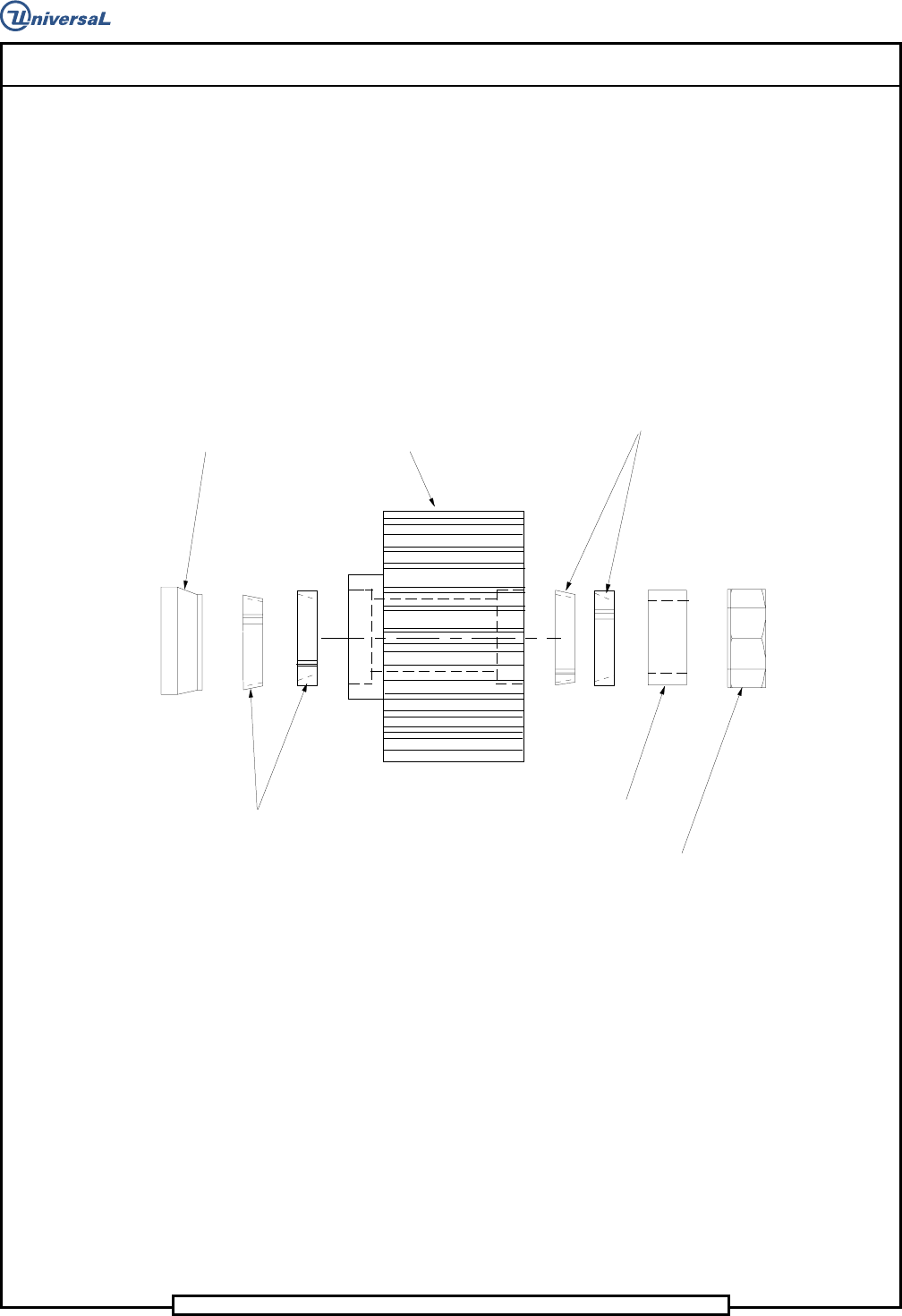
Page 11 DH P ositioning System Assembly , Non P/T T46230811 Rev . J This Document Supports Assembly 46230811 Rev J Vi ew K (Ty pi cal 2 Plac es) Spa cer Lock i ng El ement Lock i ng El eme nt He x J a m Nu t Spa cer Pul …

Page 12
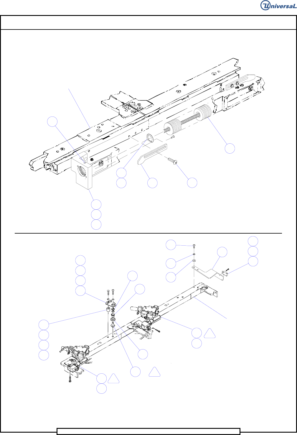
T46230811 Rev. J DH Positioning System Assembly, Non P/T
This Document Supports Assembly 46230811 Rev J
Notes
1
Torque to 90 IN - LB.
2
Apply BLKM07389 (Loctite 222) ,bottom plunger then loosen 1/4 turn.
3
Lable fittings and tubing with corresponding line numbers.
4
Electrostatic discharge precautions must be used during assembly.
5
Use Loctite 242 - UIC #BLKM07402.
6
Torque screws to 70 IN-LBS.
7
Fasten with LOCTITE 495.
8
Apply Loctite 222 - UIC #BLKM07389.
9
Replace existing set screws with hardware indicated.
10
Apply Loctite 242 (BLKM07402) to threads of ball screw units and torque nut to 15 FT- LB.
11
Set up dimension from the face of the bearing bracket to the face of the pulley hub.
12
Locate the pulley on the shaft with the set screw, then tighten the two #8 cap head screws to
secure the pulley to the shaft.
13
Orient the extended hub of the bearing to the right when viewing the shaft from the front of the
machine.
14
Do not wrap cable around encoder body.
15
Lubricate ball bushings and shaft with 10W oil after assembly. Refer to X-Y rotary positioning
assembly ball bushing lubrication procedure.
16
Completely wipe off rust preventative and apply Blue Grease (BLKM07680) thoroughly to ball
screw units.
17
Apply Megnalube (40833809) to top of plunger.
18
Dowel pins to protrude from encoder plate 0.12 inches towards motor mounting casting.
19
Keep ESD cover on connectors until cable connections are attached.
20
Torque screws to 30 IN-LBS.
21
Remove existing two 10-32 x 7/8 SHCS from lock assembly and use to attach support bracket to
lock Assembly.