46230811.pdf - 第21页
Page 19 DH P ositioning System Assembly , Non P/T T46230811 Rev . J This Document Supports Assembly 46230811 Rev J DET NO. ITEM NO. DESCRIPTION QTY U/M 186 482399001 SPACER 2 EA 187 T46230811 DOC., POSITIONING SYSTEM SUP…
Page 18
T46230811 Rev. J DH Positioning System Assembly, Non P/T
This Document Supports Assembly 46230811 Rev J
DET
NO.
ITEM NO. DESCRIPTION QTY U/M
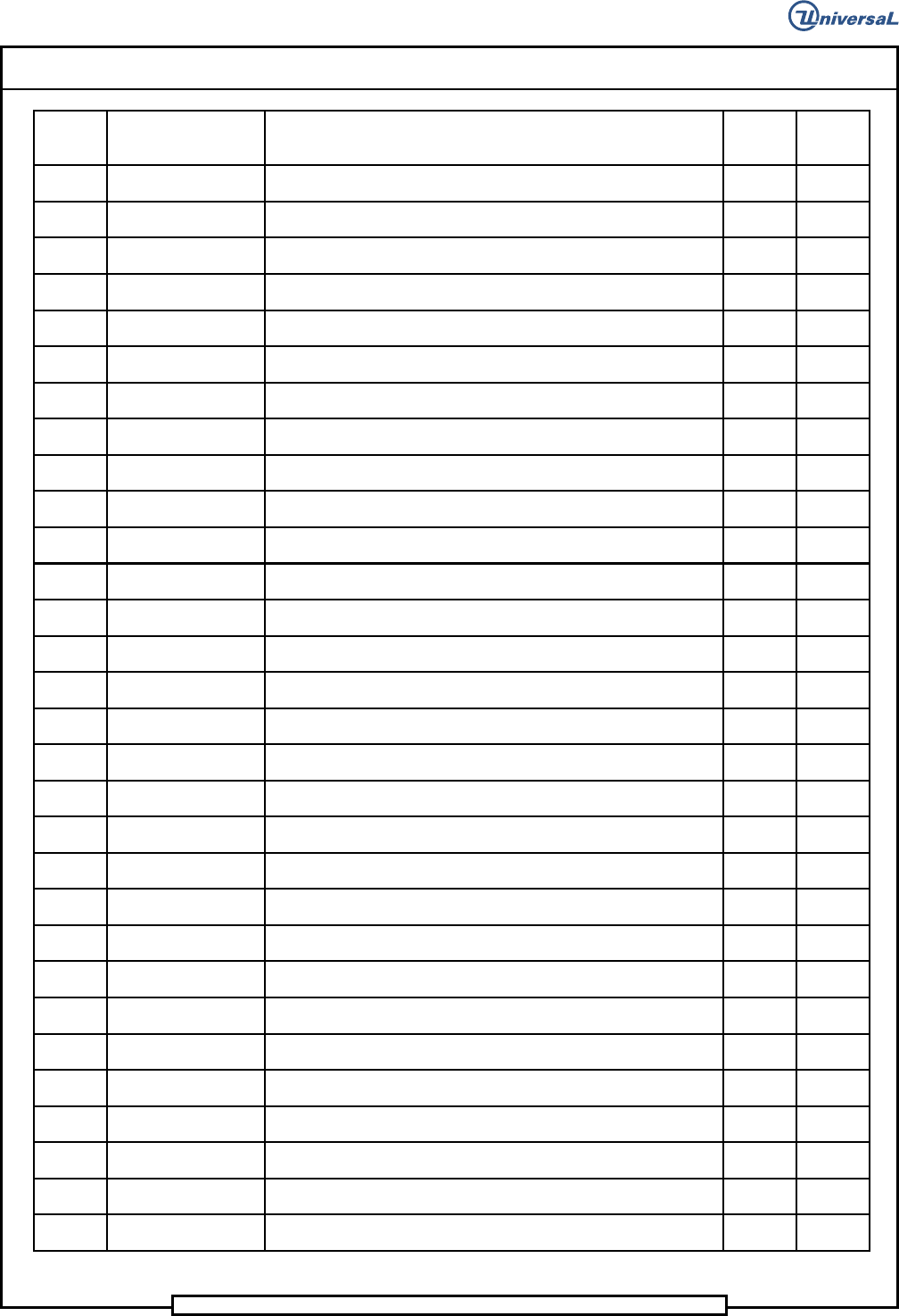
153 17258002 INSULATION .50 1 EA
154 22243002 VINYL, DAMPING 3 EA
155 44973301 BRACKET, SENSOR 2 EA
156 44460003 PROXIMITY SWITCH 2 EA
157 48236201 RETAINER, BEARING 2 EA
158 BLKM06320 RETAINING RING 2 EA
159 15179000 CLAMP,ENCODER 1 EA
160 48237501 BEARING,BALL,DOUBLE ROW 2 EA
161 48226801 PLATE,ENCODER 1 EA
162 80000407 SHCS 8-32 X 1 5 EA
163 80009904 DOWEL 1/8 DIA X 3/4 2 EA
164 46910201 ROTARY ENCODER ASSY 2 EA
165 45121802 COUPLING,FLEX 2 EA
166 80015104 HEX JAM NUT,5/16-24 2 EA
167 48236102 RETAINER, BELLOW 2 EA
168 46564806 PULLEY,GEARBELT 2 EA
169 47527101 LOCKING ELEMENT 4 EA
170 48226601 PLATE, MOTOR 1 EA
171 48257401 BRACKET 1 EA
172 30959204 DH ROT DISC ASSY 2 EA
173 80000402 SHCS 8-32 X 3/8 10 EA
174 50683801 STOP, CLAMP ASSY 2 EA
178 10249101 SPRING 4 EA
179 80010407 SDP 7/16 X 1/2 4 EA
180 80010403 SDP 7/16 X 1 1/2 2 EA
181 80000607 SHCS 1/4-20 X 1 3 EA
182 BLKE01071 CABLE CLAMP, 3/16, BLACK 2 EA
183 BLKE01079 CABLE CLAMP, 1 1 EA
184 48213801 PULLEY, MOTOR 2 EA
185 10457013 CLAMP, COLLAR 2 EA
Page 19
DH Positioning System Assembly, Non P/T T46230811 Rev. J
This Document Supports Assembly 46230811 Rev J
DET
NO.
ITEM NO. DESCRIPTION QTY U/M
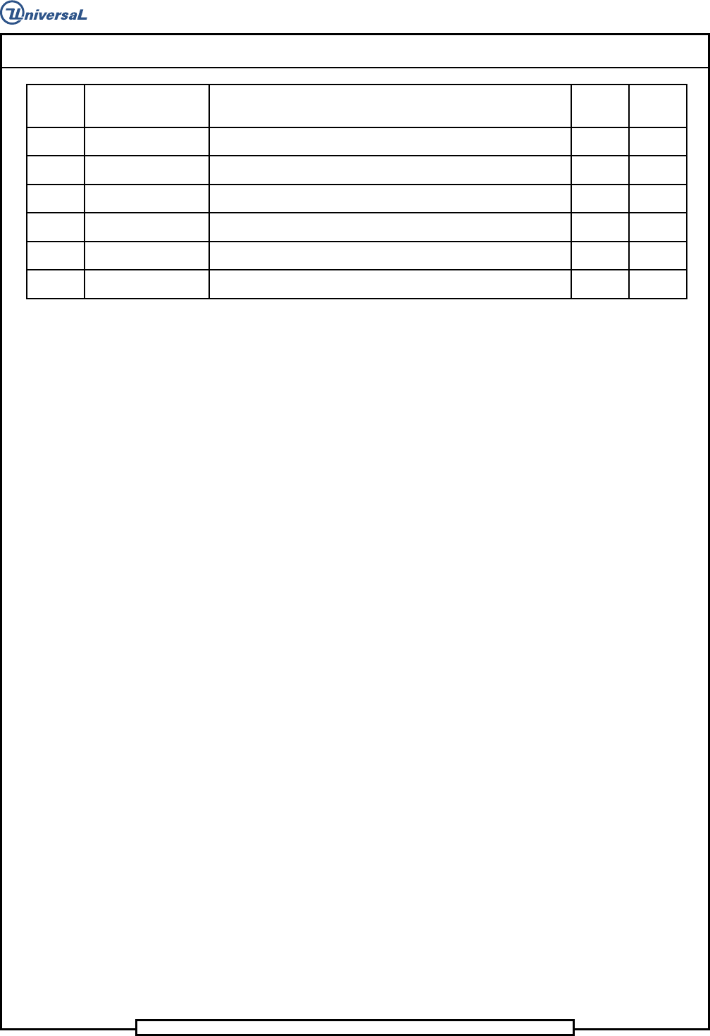
186 482399001 SPACER 2 EA
187 T46230811 DOC., POSITIONING SYSTEM SUPPORT 1 EA
188 48395101 CABLE ASSY,LIMIT WIRE 1 EA
189 80010401 SDP 7/16 X 1 2 EA
190 22243012 VINYL DAMPENING 1 EA.
191 30648505 BRACKET, SUPPORT 1 EA
Page 20
T46230811 Rev. J DH Positioning System Assembly, Non P/T
This Document Supports Assembly 46230811 Rev J
Functional Description
The dual X-Y positioning system contains the X and Y positioning tables
which are actuated by the servo drive motors. When the motors receive a
signal they move the positioning system to predetermined coordinates
contained in the pattern program. Rotary encoders monitor the positioning
system location to ensure the positional accuracy. The X and Y tables mount
on the base and position the dual rotary tables.
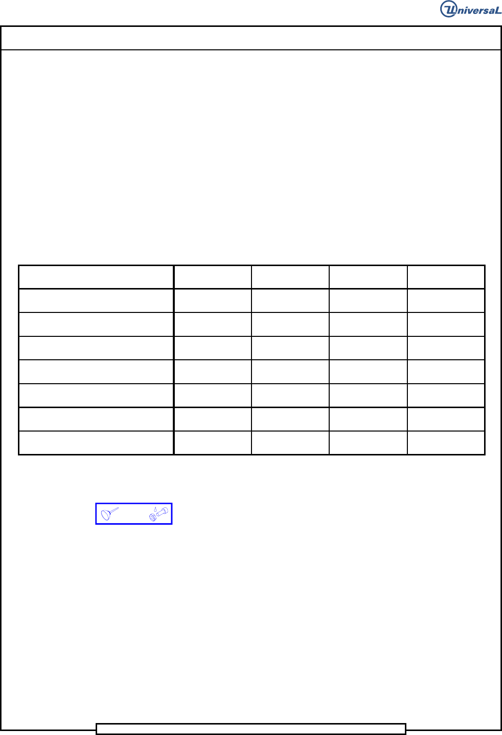
Maintenance Concept
The following table defines the recommended Maintenance Concept for this
assembly. For a more detailed explanation of the Maintenance Concept and
its structure refer to the Prerequisite Information/Introduction module and
the periodic preventive maintenance as presented later in this document.
Maintenance Procedures
Recommended
Frequency
Minimum Skill
Required
Spares Kit
Required
Tool Kit Required
Check Rotary Table squareness Weekly
Maintenance
Technician
No Yes
Check Rotary Table air motor drive wheel Weekly
Maintenance
Technician
No No
Lubricate the Rotary Table lock assembly Weekly
Maintenance
Technician
No No
Flush and Lubricate the X-Y ball bushings Monthly
Maintenance
Technician
No No
Clean and lubricate linear shafts Monthly
Maintenance
Technician
No No
Lubricate X-Y ball screws Monthly
Maintenance
Technician
No No
Diassemble, clean and lubricate Rotary
Table lock assy
Semiannually
Maintenance
Technician
No Yes
Prerequisite Information
• See the Prerequisite Information/Introduction document for Adhesive
and Lubricant icon information and definitions.