46230811.pdf - 第23页
Page 21 DH P ositioning System Assembly , Non P/T T46230811 Rev . J This Document Supports Assembly 46230811 Rev J Rotary Disc Drive Motor Mounting Procedure 1. Remove (2) 4-40 Socket Heads (SHCS) from Mounting Block and…
Page 20
T46230811 Rev. J DH Positioning System Assembly, Non P/T
This Document Supports Assembly 46230811 Rev J
Functional Description
The dual X-Y positioning system contains the X and Y positioning tables
which are actuated by the servo drive motors. When the motors receive a
signal they move the positioning system to predetermined coordinates
contained in the pattern program. Rotary encoders monitor the positioning
system location to ensure the positional accuracy. The X and Y tables mount
on the base and position the dual rotary tables.
Maintenance Concept
The following table defines the recommended Maintenance Concept for this
assembly. For a more detailed explanation of the Maintenance Concept and
its structure refer to the Prerequisite Information/Introduction module and
the periodic preventive maintenance as presented later in this document.
Maintenance Procedures
Recommended
Frequency
Minimum Skill
Required
Spares Kit
Required
Tool Kit Required
Check Rotary Table squareness Weekly
Maintenance
Technician
No Yes
Check Rotary Table air motor drive wheel Weekly
Maintenance
Technician
No No
Lubricate the Rotary Table lock assembly Weekly
Maintenance
Technician
No No
Flush and Lubricate the X-Y ball bushings Monthly
Maintenance
Technician
No No
Clean and lubricate linear shafts Monthly
Maintenance
Technician
No No
Lubricate X-Y ball screws Monthly
Maintenance
Technician
No No
Diassemble, clean and lubricate Rotary
Table lock assy
Semiannually
Maintenance
Technician
No Yes
Prerequisite Information
• See the Prerequisite Information/Introduction document for Adhesive
and Lubricant icon information and definitions.
Page 21
DH Positioning System Assembly, Non P/T T46230811 Rev. J
This Document Supports Assembly 46230811 Rev J
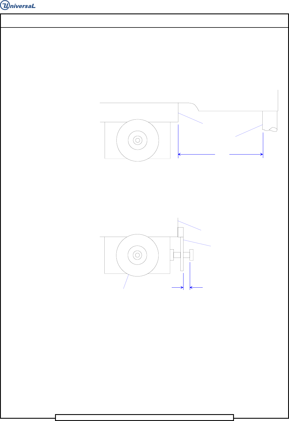
Rotary Disc Drive Motor Mounting Procedure
1. Remove (2) 4-40 Socket Heads (SHCS) from Mounting Block and
remove Drive Motor adjustment screw.
7.75"
Mounting Block
Thomson Rod
2. Mount block to X Table using the mounting hardware (10-32x1
SFHS).
3. Slide motor back onto mounting block.
.188"
Mounting Block
Stop Plate
Motor
4. Install (2) 4-40 Socket Heads, connecting stop plate to mounting
block.
Page 22
T46230811 Rev. J DH Positioning System Assembly, Non P/T
This Document Supports Assembly 46230811 Rev J
Procedures
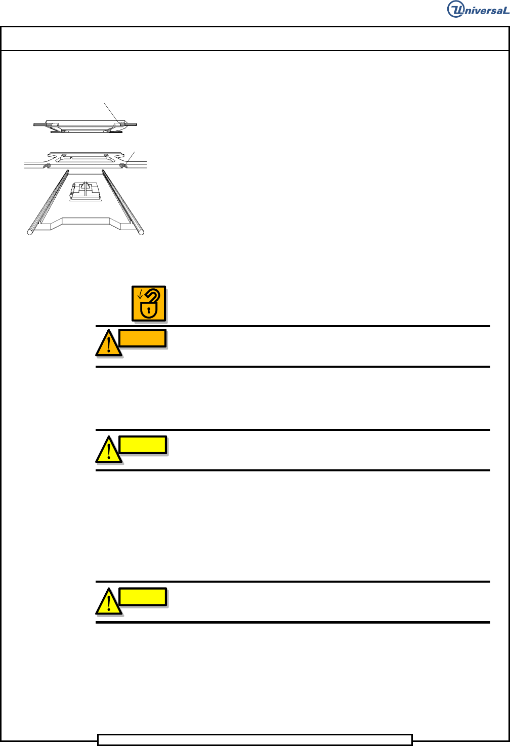
X-Y Axes Ball Bushing Preload Adjustments
The X and Y axis each have four ball bushings. The ball bushings are
located one in each corner of the table. The locations of these ball bushings
are shown below.
Initially these adjustments are done at the factory. If the ball bushings must
be replaced, the bearing preload adjustment must be performed.
1. Power down the machine and perform Lockout/Tagout according to
local procedures.
WARNING
The machine must be powered down and the local Lockout/Tagout
procedure performed to ensure personal safety during this procedure.
2. Before installing the threaded spring plunger, apply a light coat of
Loctite 222 to the threads of the spring plunger.
CAUTION
Do not allow the sealant to enter the spring plunger tip area. No curing
time is required when using this adhesive.
3. Thread the spring plunger screw slowly into the table in a clockwise
direction so the screw begins to engage the threads. Stop when
resistance is felt against the spring plunger screw.
4. While rotating the ball bushing so the screw aligns with the bushing
slot, turn the spring plunger screw in until it bottoms.
CAUTION
Do not force the spring plunger screw past the point at which it bottoms
out or damage to the ball bushing and spring plunger will occur.
5. Back the spring plunger screw out one quarter turn.
6. Repeat steps 1 through 4 for the remaining seven ball bushings.
Ball Bushing Locations
BALL
X-
Y-
BASE
BALL