46230811.pdf - 第26页
Page 24 T46230811 Rev . J DH P ositioning System Assembly , Non P/T This Document Supports Assembly 46230811 Rev J 10. Move the frame over the full range of motion for the axis noting any changes in drag on the ball scre…
Page 23
DH Positioning System Assembly, Non P/T T46230811 Rev. J
This Document Supports Assembly 46230811 Rev J
X and Y Axes Ball Screw Unit Adjustment
Alignment of the ball screw unit axes to the support bearings is critical to the
proper function of the positioning system. Improper alignment of the ball
screw nut to the corresponding axis frame may result in misalignment of the
ball screw end in relationship to the support bearings for that axis. The
following procedure is intended to minimize the misalignment and system
drag load and thereby maximize bearing life.
NOTE
Initial adjustments are done at the factory and should not be required in
the field. If the ball screw unit must be replaced in the field, the alignment
procedure must be performed.
1. Power down the machine and perform Lockout/Tagout according to
local procedures.
WARNING
The machine must be powered down and the local Lockout/Tagout
procedure performed to ensure personal safety during this procedure.
2. Thoroughly clean the frame counterbores and if necessary, clean the
threads of the ball screw unit with a tap.
3. Loosen the mounting bolts on the bearing support blocks.
4. Install the dust bellows and protective covers over each ball screw unit.
5. Slide a ball screw unit through the mating bore in the support frame
and support the ends of the ball screw unit in the respective bearings.
6. Start the threads of the nut on the ball screw unit into the frame. Screw
the threads in until just before the aligning journal on the ball screw
unit is engaged. The ball screw unit should be loose.
7. Move the frame as close as possible to the bearing support block then
tighten the mounting screws in the bearing support block. This will
locate and align the bearing support block.
8. Move the frame as close as possible to the bearing in the motor mount.
This represents the maximum bind experienced by the ball screw unit.
9. Thread the nut of the ball screw unit fully into the counterbore. Note
the ease that is required to assemble the ball screw unit. If anything
other than finger generated force is required, disassemble the ball screw
unit and start the procedure over. Otherwise, tighten the nut in the ball
screw unit fully and secure the ball screw unit in the frame using the
no-mar set screw.
Page 24
T46230811 Rev. J DH Positioning System Assembly, Non P/T
This Document Supports Assembly 46230811 Rev J
10. Move the frame over the full range of motion for the axis noting any
changes in drag on the ball screw unit. Frame movement should be
smooth for the entire range of motion.
11. Perform steps 2 through 9 for the ball screw unit on the other axis.
12. Install the drive pulleys and their protective covers for each axis then
perform the belt tension adjustment for each axis.
Rotary Disc Alignment
The rotary disc alignment procedure aligns the rotary disc to the X axis table.
Several associated assemblies rely on one another. If one assembly is
adjusted, the rest are affected. It may be necessary to alternate between one
step of the procedure and another several times until the rotary disc is
aligned.
NOTE
Read the entire rotary disc alignment procedure before attempting the
adjustment.
Rotary disc alignment is correct when, with the rotary disc locked in the
FRONT position, the dowel pins can be inserted and removed by hand
through the rotary disc and into the X axis table.
NOTE
Due to the tolerance build up, interference may be felt when inserting and
removing the pins. This is normal and in no way means the table is not
properly aligned. If the pins can not be inserted into the holes with force,
the disc is not properly aligned.
After the rotary disc is aligned, the two locator pin assemblies drop into
their corresponding locator holes. The additional pressure exerted by
the lock assembly may cause the rotary disc to shift. This shift prevents
the insertion or extraction of the guide pins and additional adjustment of
the lock assembly is required.
If the locator pins slide into the holes after the lock and drive assemblies
are in position, alignment is correct. Proceed to the X-Y axes encoder
adjustments.
Machines with Board Handling System have two low profile guide wheels
which require a special wrench and procedures. These differences are
noted as applies in the following procedure.
Page 25
DH Positioning System Assembly, Non P/T T46230811 Rev. J
This Document Supports Assembly 46230811 Rev J
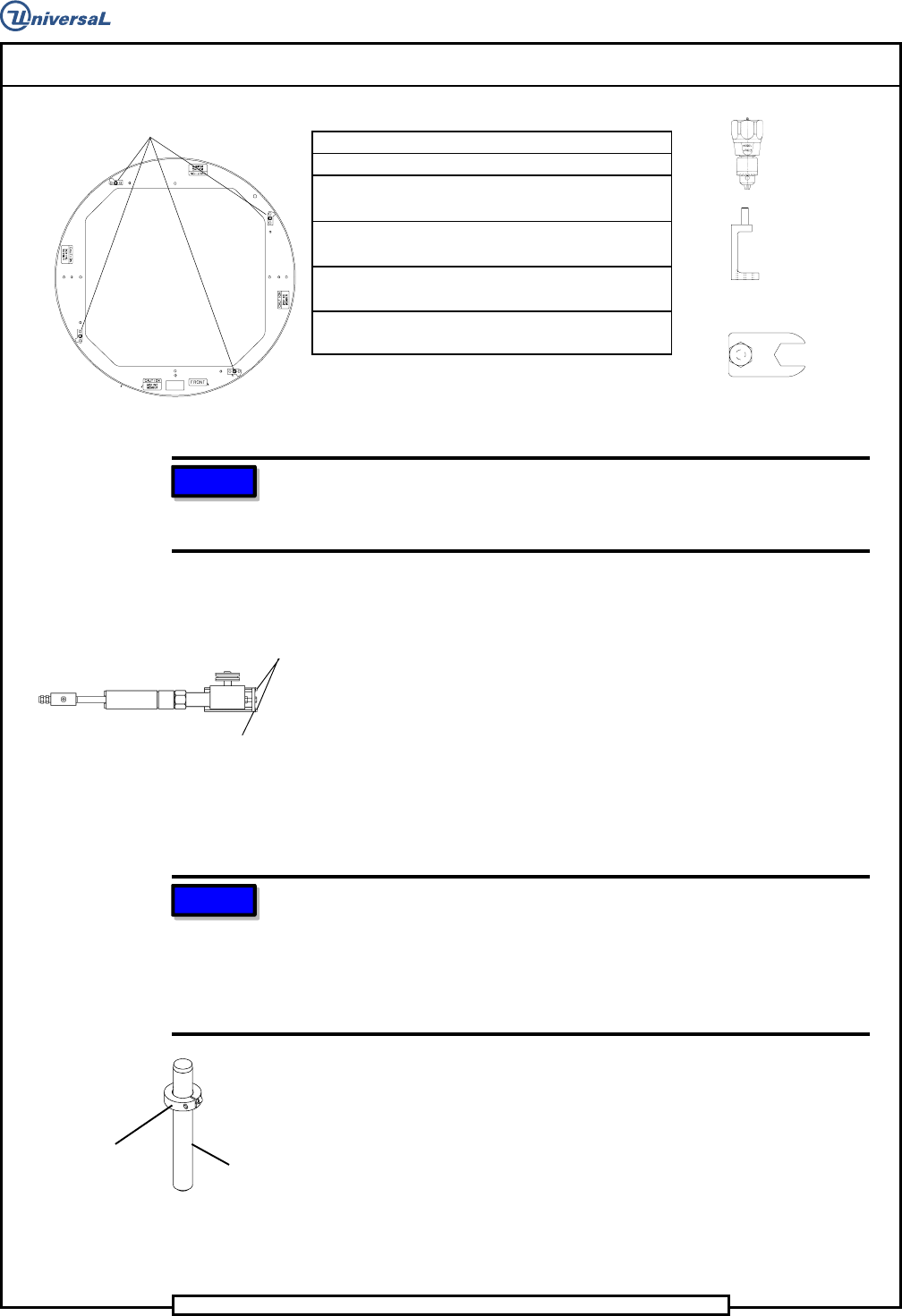
Special Tools:
Torque Wrench (in./lbs.)
Torque Gauge (in./oz.) (46808001)
(Waters Mfg. Model 651C-30)
Torque Adapter (45081601)
(High profile guide wheels)
Dowel pins (1/4 x 2) (80010109) with
collars (18333000)
Wrench (46758401)
(Low profile guide wheels)
NOTE
Depending on the machine configuration, covers and/or assembly
components will have to be removed to allow access to the guide wheels
and drive assembly.
1. Remove the four stop blocks from the rotary disc.
2. Remove the two socket head cap screws from the stop plate on the
drive assembly.
3. Remove the stop plate from the drive assembly to remove the drive
wheel pressure on the rotary disc.
4. Assemble the locator pins using dowel pins and collar clamps.
5. Insert the locator pin assemblies through the locator holes in the rotary
table and into the locator holes in the X axis table as shown.
NOTE
Due to the tolerance build up, interference may be felt when inserting and
removing the pins. This is normal and in no way means the table is not
square. If the pins can not be inserted into the holes, the disc is not
square. Some resistance may be encountered when fitting the pins into
the holes, but the resistance should never require the assistance of a
tool to remove the pins from the X axis frame.
6. If the pins can be inserted into the locator holes, proceed to step 20 to
adjust the lock assembly. If the pins can not be inserted into the
locator holes, proceed as follows.
Locator Pin Assembly
DOWEL PIN
COLLAR
CLAMP
Rotary Disk Assembly
STOP BLOCKS
Rotary Disk Drive Assembly
SOCKET
STOP