00198376-01_UM_TouchlessPlacement-R17-1_DE_EN - 第27页
Programming in SIPLACE Pro Component Shape with Placement Process "Touchless" Touchless Placement (R17-1) Ber ührungsloses Bestücken (R17-1 ) 27 3 3 P r o g r a m m in g in S I P L A C E P r o Programming in SI…
What is touchless placement of components?
Prerequisites
26 Touchless Placement (R17-1) Berührungsloses Bestücken (R17-1)
Programming in SIPLACE Pro
Component Shape with Placement Process "Touchless"
Touchless Placement (R17-1) Berührungsloses Bestücken (R17-1) 27
3
3 Programming in SIPLACE Pro
Programming in SIPLACE Pro
3.1
3.1 Component Shape with Placement Process "Touchless"
Component Shape with Placement Process "Touchless"
In order to place components "Touchless", the placement process Touchless must be assigned to the
component shape.
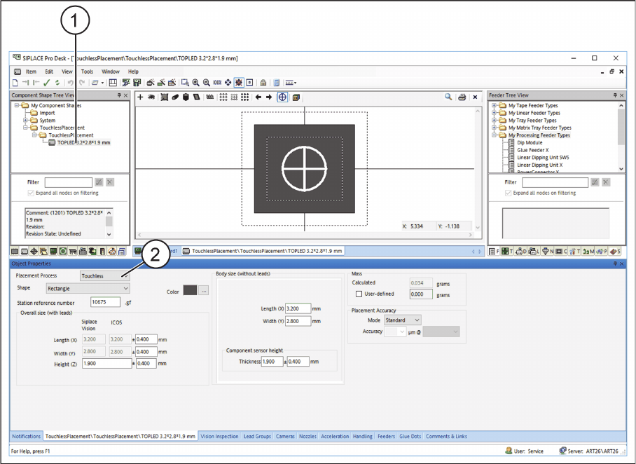
► In the Component Shape Editor in SIPLACE Pro, open the required component shape (1).
Component Shape Editor – Assigning a Placement Process
► Under Placement Process, select Touchless (2).
⇨ All components which are assigned to this component shape will be placed on the boards by means
of the Touchless placement process.
⇨ Under Placement on the Handling tab in the Component Shape Editor, the value for the Standard
force is set to 0.
⇨ At least three height measurement points must be available on the boards or grid boards to be
placed. See also "3.2 Defining Height Measurement Points" [ ➙ 29].
Programming in SIPLACE Pro
Component Shape with Placement Process "Touchless"
28 Touchless Placement (R17-1) Berührungsloses Bestücken (R17-1)
3.1.1
3.1.1 Distance between Component Lower Edge and Calculated Placement Level
Distance between Component Lower Edge and Calculated Placement Level
The Touchless placement, Z distance value is the distance between the board upper edge and the com-
ponent lower edge. This value defines the distance between the placement level and the board upper
edge in Z direction. The distance depends on the process used in the respective application and is usu-
ally defined depending on the thickness of the paste and fluxing agent.
The default value is 0.05 mm.
On the Handling tab, the distance between the component lower edge and the placement level to be
calculated can be entered in the Touchless placement, Z distance field.
► In the Component Shape Editor in SIPLACE Pro, open the required component shape.
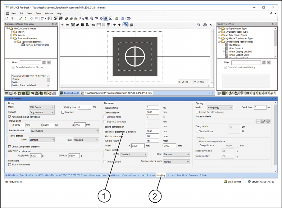
Component Shape Editor – Distance between component lower edge and calculated placement level
► Select the Handling (2) tab.
► In the Touchless placement, Z distance (1) input field, enter the distance between the component
lower edge and the calculated placement level.