00198376-01_UM_TouchlessPlacement-R17-1_DE_EN - 第34页
Placement Process at the Station Possible Errors and Corrections 34 Touchless Placement (R17-1) Berührungsloses Bestücken (R17-1) ► Check the component for damage. ► If the component is fla wless, confirm with the Compon…
Placement Process at the Station
Possible Errors and Corrections
Touchless Placement (R17-1) Berührungsloses Bestücken (R17-1) 33
4
4 Placement Process at the Station
Placement Process at the Station
After transporting the board into the station, fiducial detection takes place automatically and the defined
height measurement points are measured. The height measurement process calculates the placement
levels for contactless placement.
The placement process is started and the respective components are placed without contact.
4.1
4.1 Possible Errors and Corrections
Possible Errors and Corrections
Three error messages could occur in the station software:
32438 „Z-position out of range during height measurement“
▪Cause
– The result of the height measurement cannot be used because the difference between the ex-
pected Z height and the measured Z height of the board is too big.
▪Correction
– Make sure the board's position in the machine is planar.
▪ Correction with chuck
– Check the board height that is set in the programming system.
– Check if the correct chuck type is selected.
32439 „Slope of measured board surface is too large“
▪Cause
– The height measurement result cannot be used.
▪Correction
– Check the clamping and ensure that the board's position in the machine is planar.
– Check if the correct height measurement points are selected.
– Check whether the height measurement points lie on an interfering contour.
▪ Correction for wafer
– Check if the wafer is positioned correctly in the centering pin.
40058 „The component touched the board despite of the expected touchless placement pro-
cess“
The following causes could lead to this error:
▪ Wrong component thickness
▪ Too low level of planarity of the board or wafer
▪ The board or the wafer are not correctly picked up on the chuck / vacuum tooling (e.g. due to the
wafer centering pin).
The following procedure is carried out on the station software:
1. The station determines when the component makes contact with the board or the wafer.
2. The placement is stopped.
3. The affected placement position is set to "Unknown placement status".
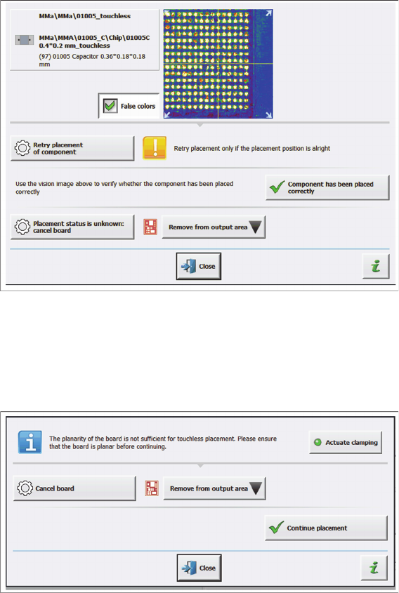
4. The message 40020 „Unknown placement status“ is shown to check the placement position:
Placement Process at the Station
Possible Errors and Corrections
34 Touchless Placement (R17-1) Berührungsloses Bestücken (R17-1)
► Check the component for damage.
► If the component is flawless, confirm with the Component has been placed correctly button.
► If a damage exists, the operator must manually remove the board from the output conveyor after
completion.
⇨ The following message on checking the placement position is displayed:
▪Correction
– Click the Actuate clamping button. The clamping of the board is released or the clamping of the
board is engaged.
– After releasing the clamping, try to align the board properly and then click the Actuate clamping
button again.
– Click the Continue placement button and the measurement points for the height check are ap-
proached and measured again to check the planarity of the board.
– In case there is still an error and the placement process is not to be continued for the entire
board, click the Cancel board button.
Tips
Touchless Placement (R17-1) Berührungsloses Bestücken (R17-1) 35
5
5 Tips
Tips
Head steps for the measurement of height measurement points
▪ Head steps for the measurement of height measurement points are only generated by the SIPLACE
Pro optimization process if components with the Touchless placement process are available on the
board. Otherwise, the defined height measurement points will be ignored.
▪ Generated head steps for measuring the height measurement points are listed with the
"HEIGHT_MEASURE" type on the Head Steps tab in the Recipe Analyzer tool of the SIPLACE Pro
Optimizer Toolkit.