YS24X_Ope_E.pdf - 第101页
2-26 2 asic operation 3.4.1 Conveyor unit setup flow Set up the convey units as sho wn in the flowc hart below . Adjust conveyor width Set board on conveyor [Conveyor] ON [Mount Position] ON Dual - stage Arrange push-u…
2-25
2
asic operation
3.4 Adjusting the conveyor unit setup
When the board type to be produced is changed, the conveyor unit setup must be adjusted, and the feeders
prepared to match that board type. This section describes how to change the conveyor unit setup.
n
NOTE
When producing boards using both lanes of dual-lane machines, use the lane select button to select the lane to be
operated and then adjust or check the conveyor unit setup.
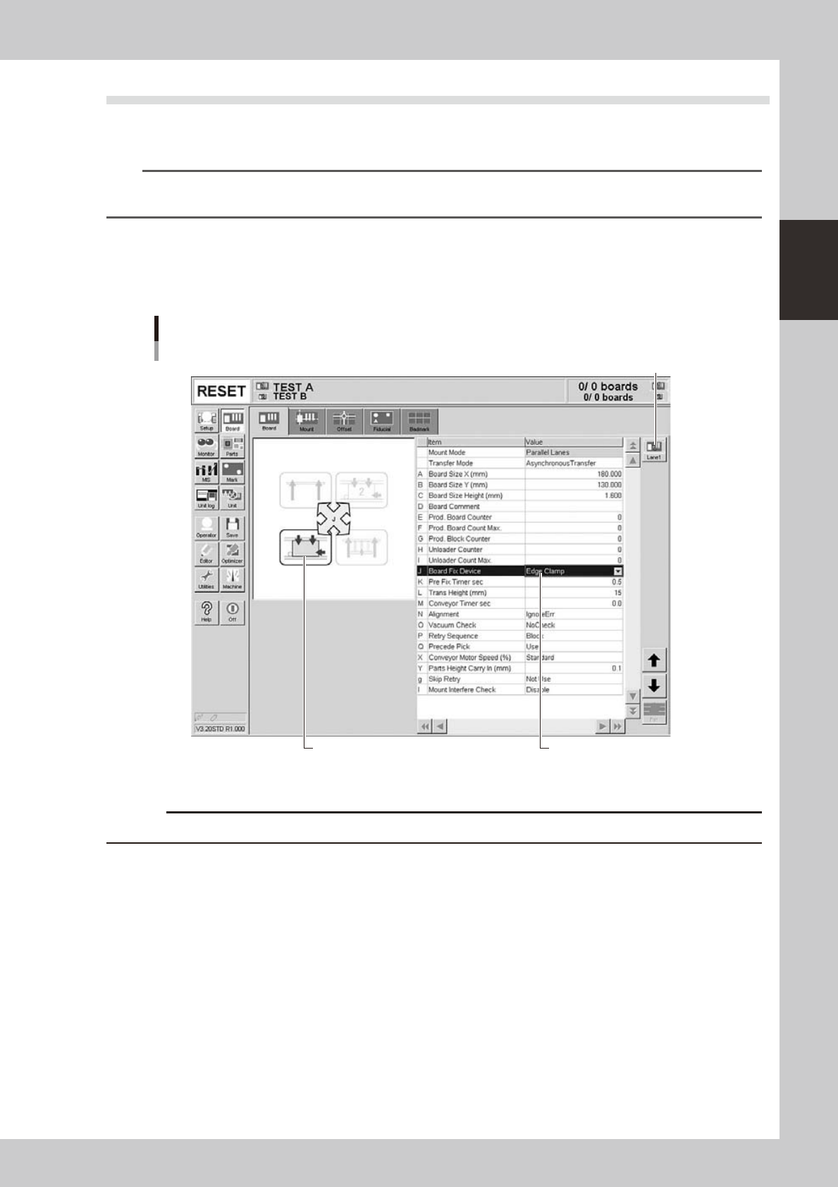
Board clamping method
Select "Edge Clamp" for the board clamping method. This method clamps a board by pushing up its edges against the
board hold plates. Push-up pins are also used to support the board at points other than its edges.
Board clamping method
Checking board clamp method
Illustration shows how board
is clamped on the conveyor.
Lane select button
24218-L4-10
c
Conveyor's board sensors may fail to detect a production board if it has a slit or cutout.
2-26
2
asic operation
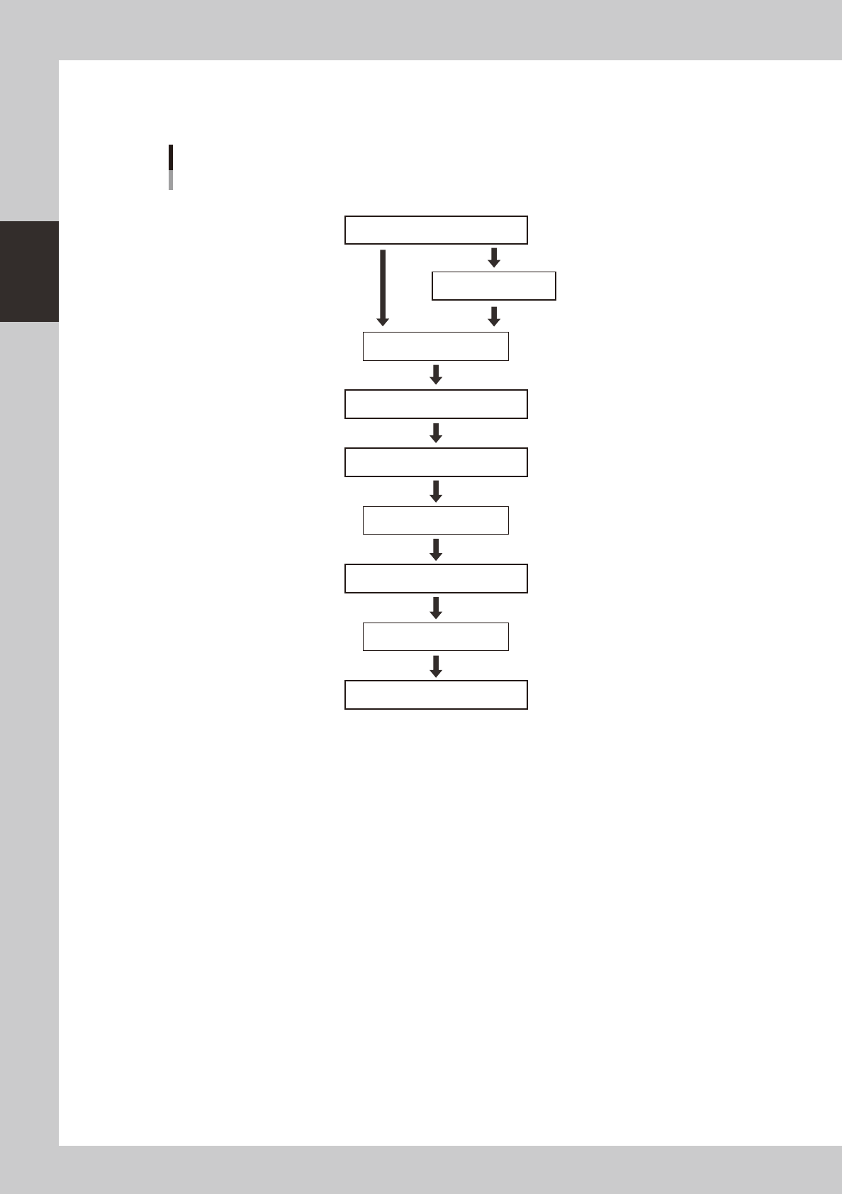
3.4.1 Conveyor unit setup flow
Set up the convey units as shown in the flowchart below.
Adjust conveyor width
Set board on conveyor
[Conveyor] ON
[Mount Position] ON
Dual - stage
Arrange push-up pins
[Push Up] ON
[Push Up] OFF
Press emergency stop button
Remove board
Press emergency stop button
Press emergency stop button
Cancel emergency stop
Move to setup position
Conveyor unit setup flow
Conveyor
Single - lane
Dual - lane
23203-L4-10
1
Adjust the conveyor width.
After selecting the board data, open the [Unit]-[Conveyor] tab and press the [Width] button. Check the
conveyor width shown in the "Conveyor Width" dialog box that appears, and press the [OK] button. The
conveyor width changes to the specified width.
2
Move the conveyor to the setup position. (when Dual - stage is used)
Press the [Mount Position] button to move the conveyor to the setup position. The conveyor of stage 2
will move to the rear.
e
3
Press the emergency stop button and open the safety cover.
4
Set a board on the conveyor.
2-27
2
asic operation
5
Place the push-up pins in the correct positions on the push-up plate.
Push-up pins are attached on the push-up plate by magnet. Considering the shape and size of the
board, place the push-up pins on the push-up plate so that they uniformly support the board, including
the edge of the board.
c
Set the push-up pins in positions where they will not interfere with the conveyor rails and other parts when the push-up
not change this height.
n
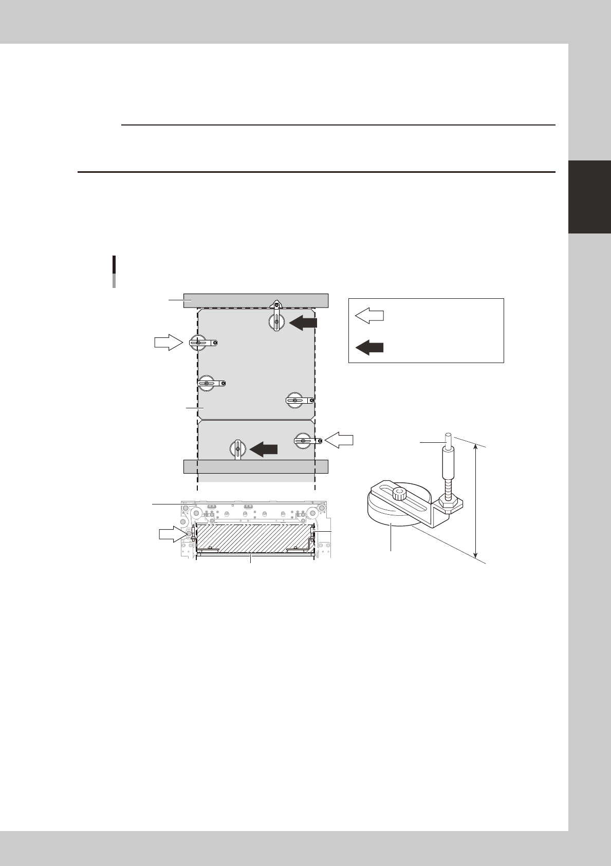
Precautions when positioning the dual-stage
When positioning the dual stage (one board on each stage), be especially aware of where push-up pins are arranged on
stage 2. By referring to the figure below, arrange push-up pins on the stage so that they do not protrude from the push-up
plate.
OK
OK
OK
NG
NG
NG
NG
NG
NG
NG
NG
76mm
Support pin
Push-up pin
Height and arrangement (stage 2)
Magnet stand
Conveyor
frame
Conveyor
frame
Push-up
plate
Push-up pin is under the conveyor
frame.
Push-up pin or magnet stand
protrudes from the left or right
edge of push-up plate
(area enclosed by dotted line).
Push-up pin
Push-up plate
23204-L4-10