YS24X_Ope_E.pdf - 第102页
2-27 2 asic operation 5 Place the push-up pins in the correct positions on the push-up plate. Push-up pins are attached on the push-up plate by magnet. Considering the shape and size of the board, place the push-up pin…
2-26
2
asic operation
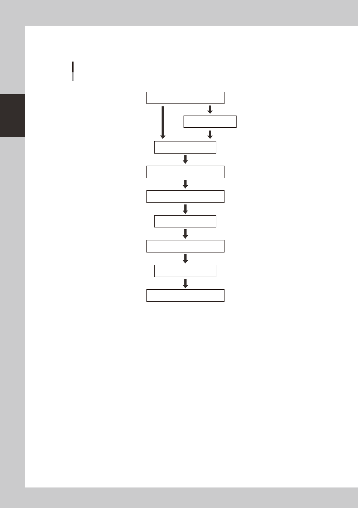
3.4.1 Conveyor unit setup flow
Set up the convey units as shown in the flowchart below.
Adjust conveyor width
Set board on conveyor
[Conveyor] ON
[Mount Position] ON
Dual - stage
Arrange push-up pins
[Push Up] ON
[Push Up] OFF
Press emergency stop button
Remove board
Press emergency stop button
Press emergency stop button
Cancel emergency stop
Move to setup position
Conveyor unit setup flow
Conveyor
Single - lane
Dual - lane
23203-L4-10
1
Adjust the conveyor width.
After selecting the board data, open the [Unit]-[Conveyor] tab and press the [Width] button. Check the
conveyor width shown in the "Conveyor Width" dialog box that appears, and press the [OK] button. The
conveyor width changes to the specified width.
2
Move the conveyor to the setup position. (when Dual - stage is used)
Press the [Mount Position] button to move the conveyor to the setup position. The conveyor of stage 2
will move to the rear.
e
3
Press the emergency stop button and open the safety cover.
4
Set a board on the conveyor.
2-27
2
asic operation
5
Place the push-up pins in the correct positions on the push-up plate.
Push-up pins are attached on the push-up plate by magnet. Considering the shape and size of the
board, place the push-up pins on the push-up plate so that they uniformly support the board, including
the edge of the board.
c
Set the push-up pins in positions where they will not interfere with the conveyor rails and other parts when the push-up
not change this height.
n
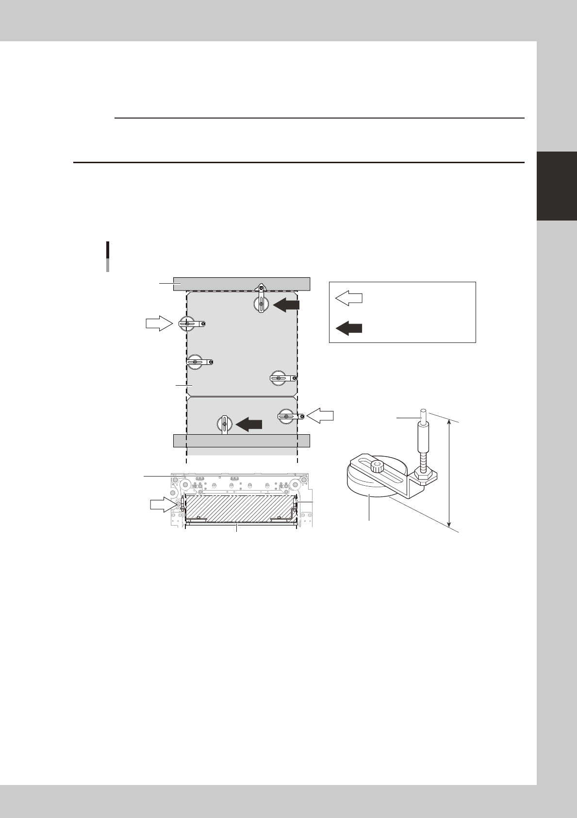
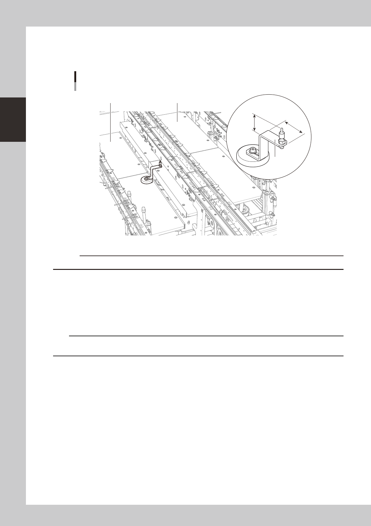
Precautions when positioning the dual-stage
When positioning the dual stage (one board on each stage), be especially aware of where push-up pins are arranged on
stage 2. By referring to the figure below, arrange push-up pins on the stage so that they do not protrude from the push-up
plate.
OK
OK
OK
NG
NG
NG
NG
NG
NG
NG
NG
76mm
Support pin
Push-up pin
Height and arrangement (stage 2)
Magnet stand
Conveyor
frame
Conveyor
frame
Push-up
plate
Push-up pin is under the conveyor
frame.
Push-up pin or magnet stand
protrudes from the left or right
edge of push-up plate
(area enclosed by dotted line).
Push-up pin
Push-up plate
23204-L4-10
2-28
2
asic operation
n
Precautions when positioning the dual-lane
The push-up pins for the dual-lane are specially designed to avoid the interference with the push-up plate.
The component taller than 20mm at the bottom side of the board may interfere with the "AA" part in the picture below.
PU1 (Fromt side)PU2 (Rear side)
23.7mm
41mm
AA
Push-up pin
Dual -lane
23236-L4-00
c
Please do not use the push-up pins from other machines to a dual-lane machine.
6
Raise the push-up plate.
Ensure safety, cancel emergency stop, and then press the [Push Up] button on the "Conveyor" screen.
Select the lane in case of the dual-lane machine. The push-up plate moves up to clamp the board.
7
Check that the board is uniformly clamped on the conveyor.
Lightly tap on the board and also check for warping of the board from the side. If the board is
supported evenly with no warping, the adjustment is okay.
TIP
It may be convenient to mark the positions of the push-up pins on the plate (with a label, magic marker, etc.) for each
board type.
e
8
Remove the board from the conveyor.
Press the [Push Up] button on the "Conveyor" screen to lower the push-up plate, press the emergency
stop button, and then remove the board. Select the lane in case of the dual-lane machine.