YS24X_Ope_E.pdf - 第104页
2-29 2 asic operation 4. Preparing the component supply unit 4.1 T ape feeders 4.1.1 Setting the tape c Always use a temporary tape set station or a power station for the of f-line setup to set the tape. The ta…
2-28
2
asic operation
n
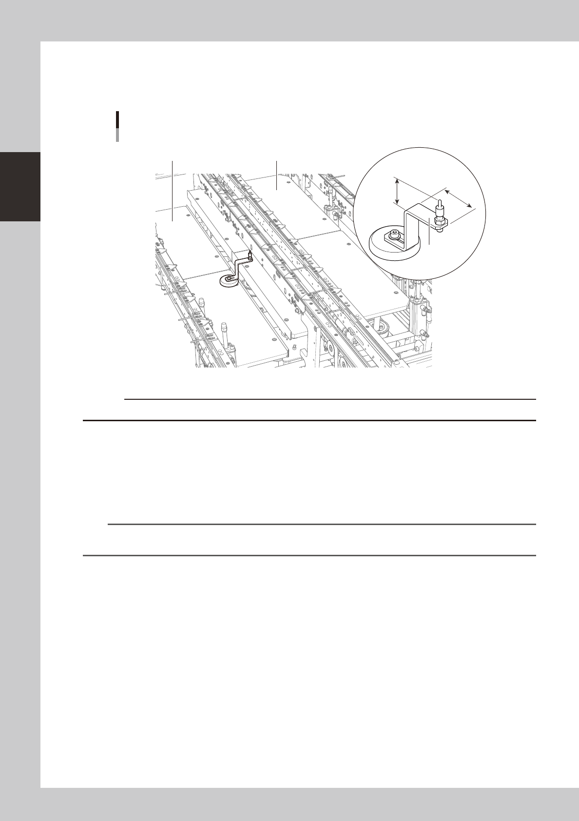
Precautions when positioning the dual-lane
The push-up pins for the dual-lane are specially designed to avoid the interference with the push-up plate.
The component taller than 20mm at the bottom side of the board may interfere with the "AA" part in the picture below.
PU1 (Fromt side)PU2 (Rear side)
23.7mm
41mm
AA
Push-up pin
Dual -lane
23236-L4-00
c
Please do not use the push-up pins from other machines to a dual-lane machine.
6
Raise the push-up plate.
Ensure safety, cancel emergency stop, and then press the [Push Up] button on the "Conveyor" screen.
Select the lane in case of the dual-lane machine. The push-up plate moves up to clamp the board.
7
Check that the board is uniformly clamped on the conveyor.
Lightly tap on the board and also check for warping of the board from the side. If the board is
supported evenly with no warping, the adjustment is okay.
TIP
It may be convenient to mark the positions of the push-up pins on the plate (with a label, magic marker, etc.) for each
board type.
e
8
Remove the board from the conveyor.
Press the [Push Up] button on the "Conveyor" screen to lower the push-up plate, press the emergency
stop button, and then remove the board. Select the lane in case of the dual-lane machine.
2-29
2
asic operation
4. Preparing the component supply unit
4.1 Tape feeders
4.1.1 Setting the tape
c
Always use a temporary tape set station or a power station for the off-line setup to set the tape. The tape cannot be
set directly on the mounter.
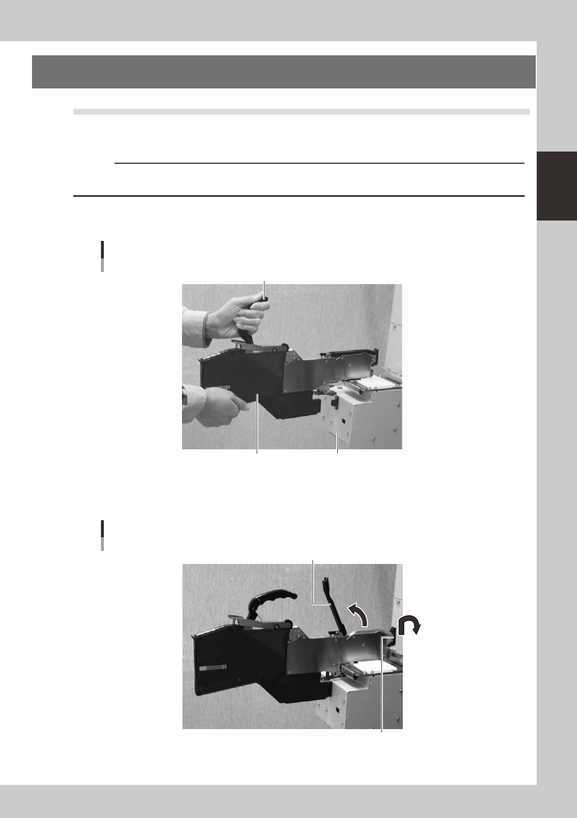
1
Set the feeder.
Place the feeder in the temporary tape set station or power station for the off-line setup.
Setting the feeder
Handle
Feeder Temporary tape set station
23205-L4-00
2
Raise the tape guide assembly.
Lower the front lever for the tape guide while lifting it, and raise the tape guide assembly.
Raising the tape guide assembly
Tape guide assembly
Tape guide front lever
23206-L4-00
2-30
2
asic operation
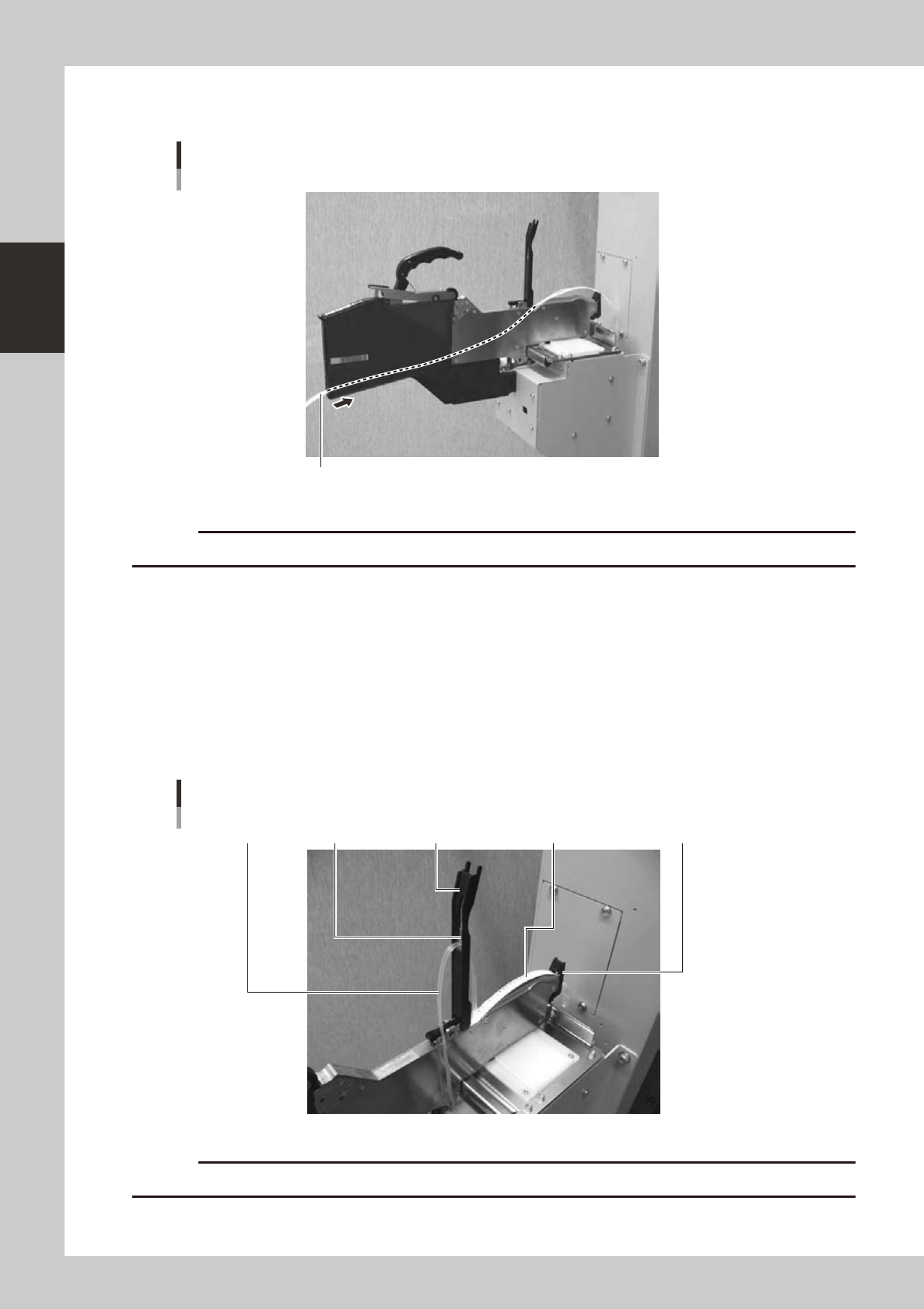
3
Set the tape in the tape feeder.
Insert in the hole on the rear of the feeder.
Mounting the tape
Tape
23207-L4-00
c
4
Peel off the top tape.
The tape consists of 2 layers. One is a "carrier tape" holding the electronic component and the other is a
"top tape" covering the upper surface of the component. Peel off the top tape.
5
Set the carrier tape.
Run the carrier tape through the hole in the tape guide front lever.
6
Set the top tape.
Run the top tape through the notch in the tape guide assembly. Be sure to pull out enough tape so the
top tape reaches the take-up roller.
Carrier tape and top tape
Top guide assemblyBottom plateTop tape Carrier tape Tape guide front lever
23208-L4-00
c