YS24X_Ope_E.pdf - 第113页
2-38 2 asic operation 4.1.3 Installation on a mounter Observe the following instructions for installing the tape feeder on a mounter . e 1 Pr ess the emergency stop button and then open the cover . Press the emergency …
2-37
2
asic operation
3
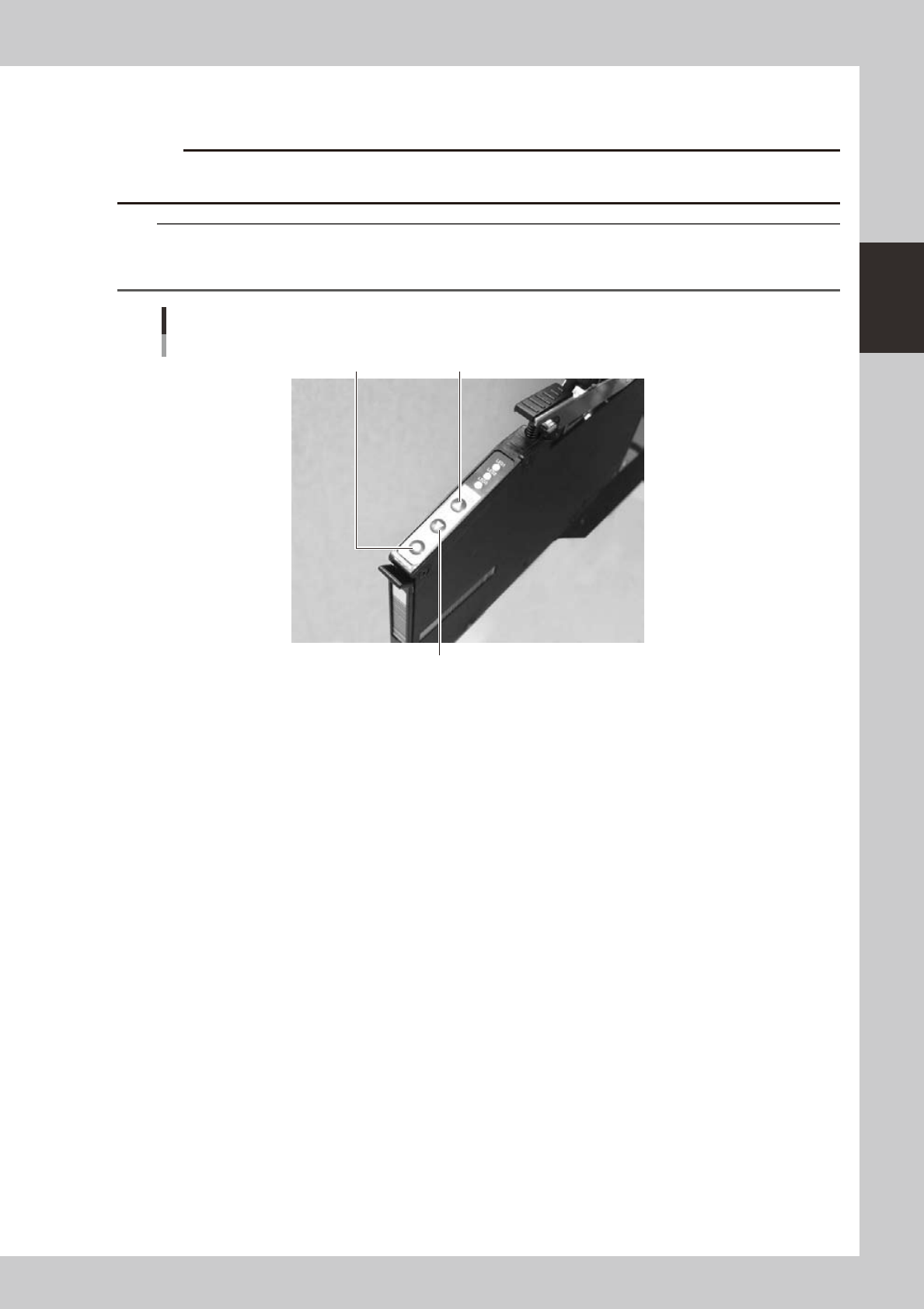
Check the tape feed operation.
Press the [FEED] button on the feeder body to check that the tape is fed at the correct pitch.
c
advance the carrier tape.
TIP
• The feed pitch will always be 2 mm each time the [FEED] or [BACK] button on the feeder body is pressed,
regardless of the pitch setting. Holding down either of these buttons feeds the tape continuously.
• Use the [FUNC]+[FEED] buttons to feed the tape at the feed pitch that was set.
Checking the feed pitch
[BACK] button
[FEED] button[FUNC] button
23215-L4-00
2-38
2
asic operation
4.1.3 Installation on a mounter
Observe the following instructions for installing the tape feeder on a mounter.
e
1
Press the emergency stop button and then open the cover.
Press the emergency stop button on the mounter to stop mounter operation.
c
it.
2
Clean the surface of the feeder bank.
Parts or debris caught in the machine will tilt the feeder, interfering with stable pickup.
3
Place the tape reel in position of the reel holder.
Tape reels can be placed alternately in the upper and lower reel holders.
4
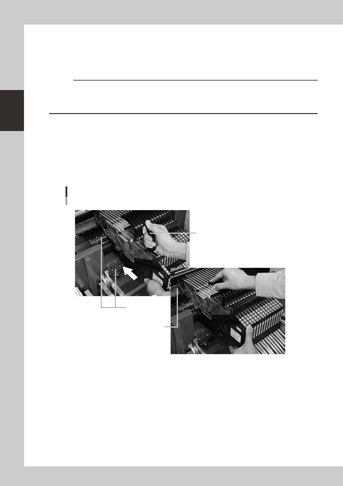
Set the feeder.
Raise the handle, align the target mark to the feeder installation position, and slide the feeder on the
rail to insert it to the location pin hole.
Attachment of the feeder
Tape feeder
Handle part
Rail
Location pin hole
22226-L4-00
5
Check the following points to make sure that the feeder is properly installed.
• Top tape is no loose.
• Feeder is properly inserted all the way.
2-39
2
asic operation
4.2 Wide multi-stick feeder
4.2.1 Installation of tracks and sticks
1
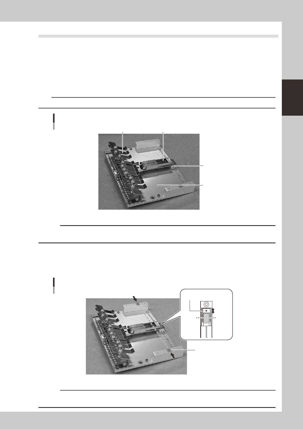
Install the tracks on the slope plate.
Place the tracks of the right width for the sticks you desire to use on the slope plate and secure them
with screws.
If the height of the tracks is lower than that of the slope plate, fit the spacers (provided with unit)
between the tracks and slope plate so that the pickup height will be the same.
n
NOTE
For detailed information on the pick height and stick height, refer to the User’s Manual for SS feeder.
Installation of the tracks
Slope plate
Spacer
Track
Stick restraint
23217-L4-00
c
as collision with the head.
2
Adjust the stopper position.
The line shown in the illustration below is the component pickup point.
Loosen the screws on the back of the tracks and adjust the stoppers to match the pickup point and the
center of the component.
Pickup point
Pickup point
Line
Stopper
Pickup
point
23218-L4-00
c
Use supply components of 36 mm or less in length. Components longer than 36 mm cannot be supplied when the
feeder operates.