YS24X_Ope_E.pdf - 第116页
2-41 2 asic operation n If sticks are loose or deflect too much T he flat spring of the stick restraint B should be adjusted. Loosen the screws securing the flat spring of the stick restraint B and adjust the position …
2-40
2
asic operation
3
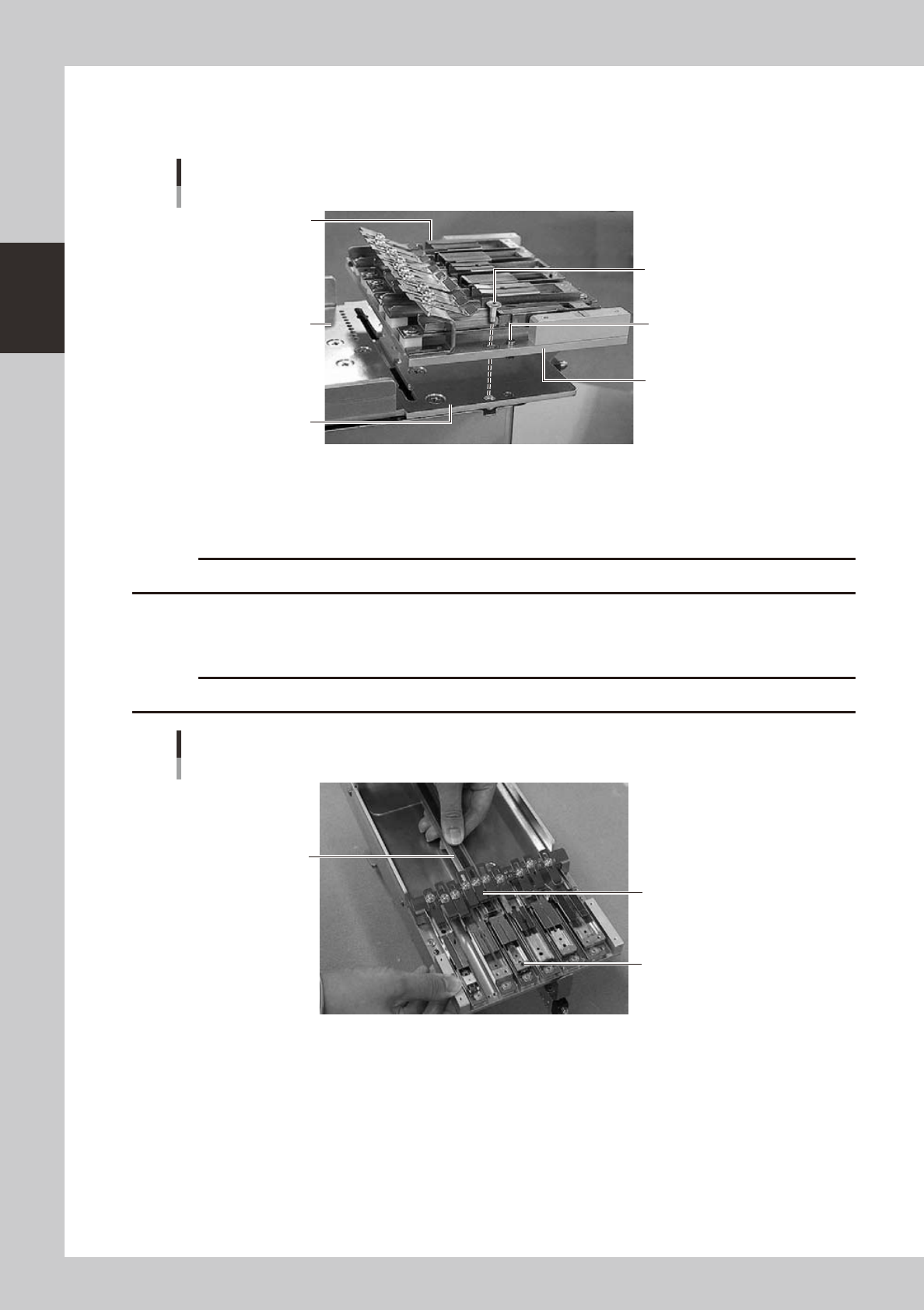
Install the slope plate on the feeder.
Insert the knock-pin of the slope plate to the upper plate and secure two positions with the slope plate
securing screws.
Installation of the slope plate
Slope plate
Knock-pin
Slope plate securing
screw
Slope plate securing
screw
Upper plate
Feeder
23220-L4-00
4
Remove rubber pieces from sticks.
Rubber pieces are attached to the both ends of stick-type components to maintain electronic
components in place. Remove these rubber pieces before use.
c
Handle carefully so that electronic components do not fall out of the sticks.
5
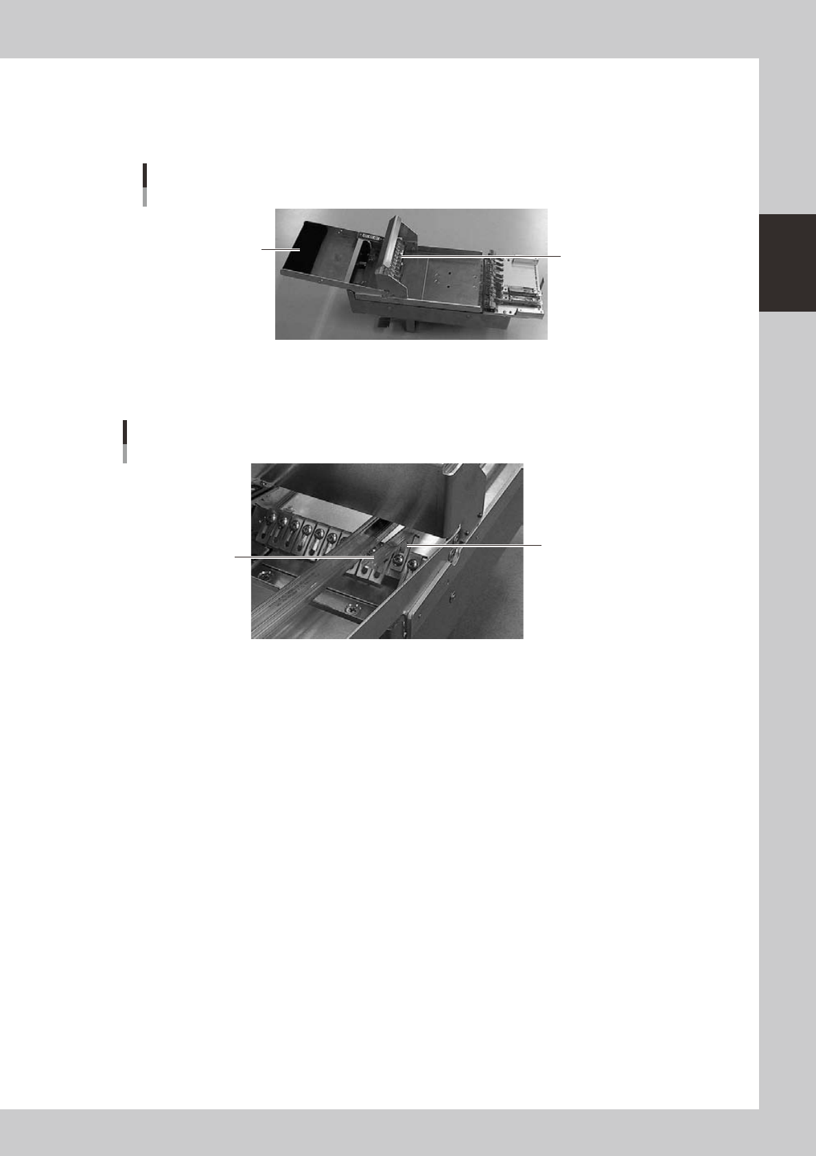
Insert the sticks in the tracks.
Pass the stick under the stick restraint as shown in the illustration below to insert the stick to the track.
c
Install the components in the correct direction with the correct side up.
Insertion of the sticks
Stick Restraint A
Stick
Track
23221-L4-00
2-41
2
asic operation
n
If sticks are loose or deflect too much
The flat spring of the stick restraint B should be adjusted.
Loosen the screws securing the flat spring of the stick restraint B and adjust the position of the flat spring so that
appropriate tension is added to the sticks, and tighten the screws.
Stick restraint
Stick support
Stick restraint B
23222-L4-00
n
If sticks are too short to reach the stick support
Raise the adjustment plate as shown in the illustration below to support the stick from below.
Adjustment plate
Stick
Adjustment plate
23223-L4-00
2-42
2
asic operation
4.2.2 Installation on a mounter
Observe the following instructions for installing the wide multi-stick feeder on a mounter.
e
1
Install the tracks on the slope plate.
Press the emergency stop button on the mounter to stop mounter operation.
c
2
Clean the surface of the feeder bank.
Parts or debris caught in the machine will tilt the feeder, interfering with stable pickup.
3
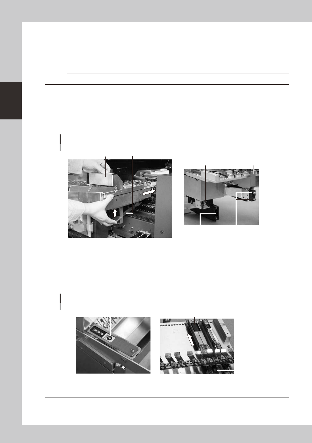
Set the feeder.
Raise the clamping lever, align the target mark to the feeder installation position and slide it to insert it
to the location pin hole.
Attachment of the feeder
Clamping lever
Connector for power/signal
Location pin
Tail pin
Target mark
Handle part
23224-L4-00
4
Check the assembled condition.
Release the clamping lever and try to move the feeder back and forth to check if it is fixed securely.
5
Set components.
Press the [FEED] button so that the first component reaches the pickup position. The feeder will vibrate
for two seconds to feed components at the touch of the button.
Confirmation of operation and setting components
First component
Stick
[FEED] button
23225-L4-00
TIP
For detailed information on the wide multi-stick feeder, refer to the User’s Manual for SS feeder.