YS24X_Ope_E.pdf - 第157页
3-25 3 Starting and ending pr oduction 3.9 Pick Pos. (Pickup position of fset) T his screen appears when the pickup position offset function is used. This screen sho ws how the pic kup position of the target component wa…
3-24
3
Starting and ending production
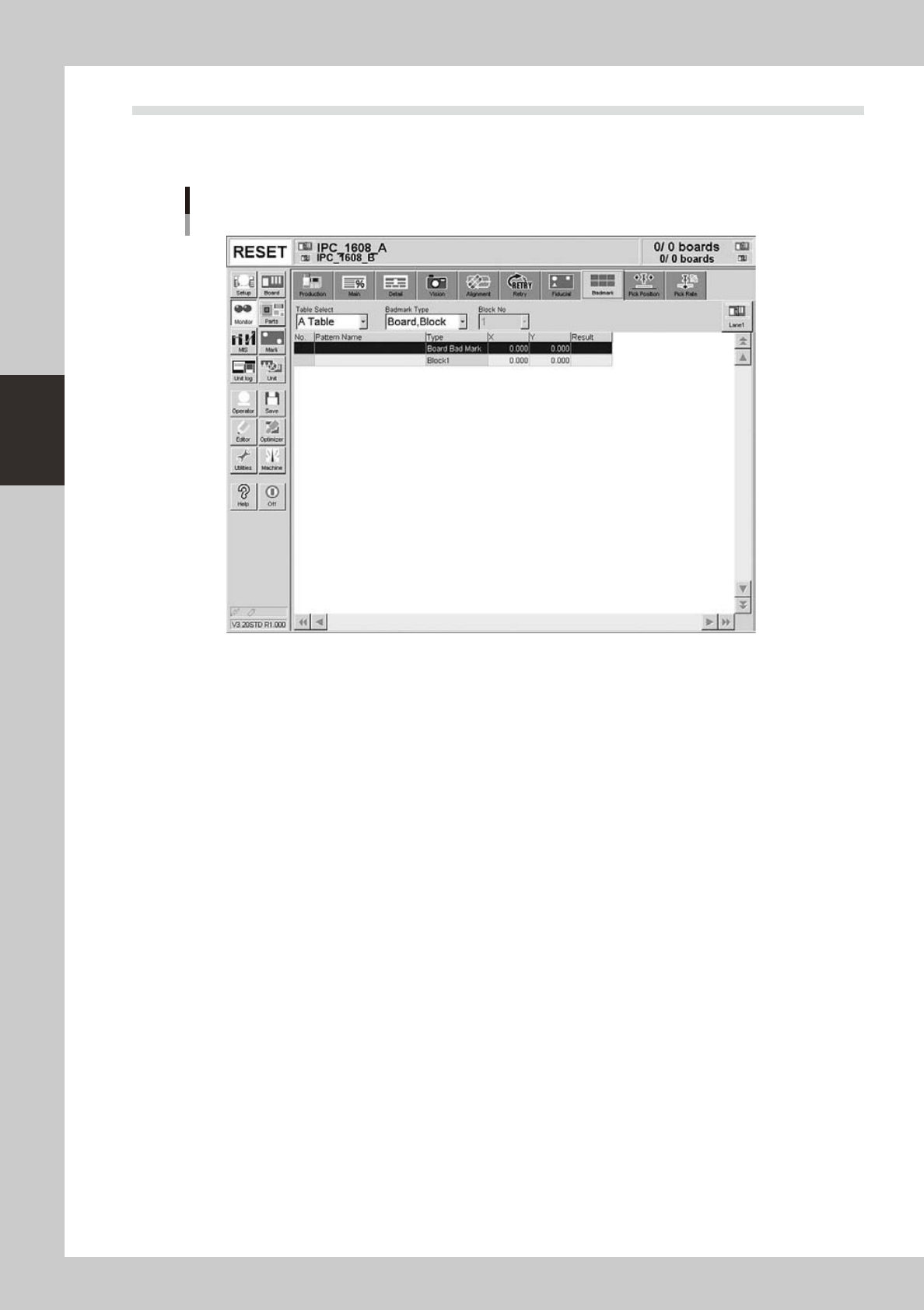
3.8 Badmark
The [Badmark] tab screen shows the recognition results of badmarks such as "Board, Block" and "Local"
badmarks.
Monitor: Badmark
Example of Dual-lane
24316-L4-10
• X, Y
Shows the board data input values (by taking block offset amount into account).
• Result
Makes an "OK" or "NG" decision based on the badmark recognition result.
OK : Work is performed when no badmark is recognized.
NG : Work is not performed when a badmark is recognized.
3-25
3
Starting and ending production
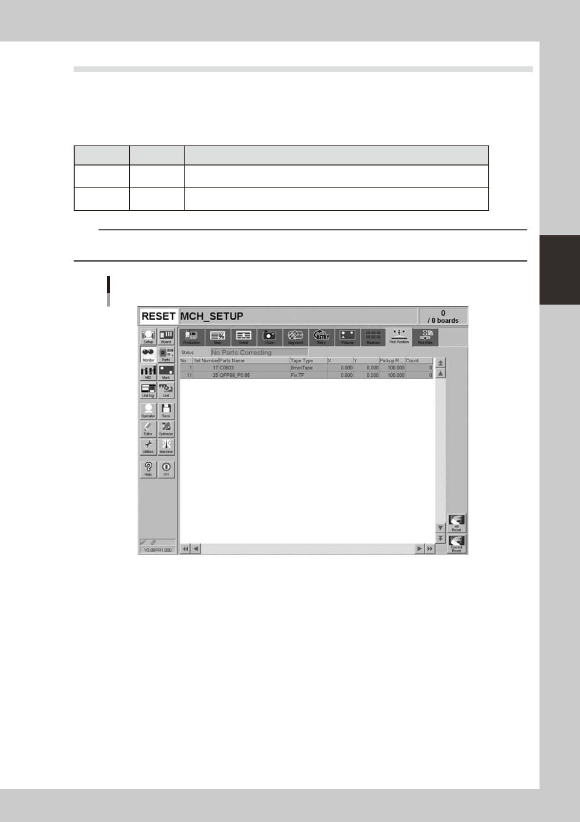
3.9 Pick Pos. (Pickup position offset)
This screen appears when the pickup position offset function is used. This screen shows how the pickup
position of the target component was corrected or offset. When the amount of offset in either the X or Y
direction crosses into a warning zone or error zone, the color of that row changes in real-time. The monitor
display color is shown below.
n
Display color
Color of row Status Description
Yellow Warning
Exceeds warning level figure for each nozzle data set in pickup position offset
specifications.
Red Error
Exceeds error level figure for each nozzle data set in pickup position offset
specifications.
n
NOTE
Numerical values for warning level and error levels set in the pickup position offset specifications are values
determined by the supervisor (administrator).
Monitor: Pick Pos. (Pickup position offset)
24317-L4-00
• No.
Displays the component No. (Parts screen data No.).
• Set No.
Displays the feeder set No.
• Parts Name
Displays the component name.
• Tape Type
Displays the type type.
• X (mm), Y (mm)
Displays the amount of pickup position offset after recognition. The figure shown is the amount of error from the nozzle
center position towards the X-direction and Y-direction.
• Pick Rate (%)
Displays the component pickup rate of the nozzle for which the pickup position offset function is on (enabled).

3-26
3
Starting and ending production
• Count
Displays the number of components that were picked and placed by the nozzle for which the pickup position offset
function is on (enabled).
• [All Reset] button
This button clears and resets pickup position offset data for all components shown on the monitor.
• [Current Reset] button
Clears and resets pickup position offset data for a component selected from among components shown on the monitor.