YS24X_Ope_E.pdf - 第37页
Chapter 1 Par t names and functions Contents 1 3 2.1 Keyboard and mouse 1- 3 4 3. Head assembly 1- 5 3.1 Componen…
iv
About this manual
3. Page layout
The description below shows a typical page layout used in this manual.
2-32
2
Basic operation
4.2 Finishing board production
To finish board production, follow these steps.
Stop machine operation.
The re are four methods for stopping the machine.
1. Emergency st op button:
Press this button to trigger emergency stop. Do not use this button in nor mal operation.
2. [STOP] but ton (operation panel):
Pressing the [STOP] b utton stops the machine immediately. To resume o peration, press the [START]
but ton on the operation panel.
3. [Cy cle Stop] button:
Pressing this button stops the machine op eration just after component mounting on the current
board has been completed.
4. [Co nvey-out stop] button:
Use this button when you want to finish p roduct
ion just after component s have been mounted on
the board currently on th e conveyor. All boards on the conveyor are carried out after component
mountin g, but new boards are not carried in from the up stream side.
CAUTION
Do not press the emergency stop button during operation except in case of emergency.
Reset the operation.
Press the [RESET] button on the operation panel. The machine stops operation immediately and returns
to the board production standby status.
Press the [Off] button on the screen.
[Off] button
[Off] button
24226-F9-00
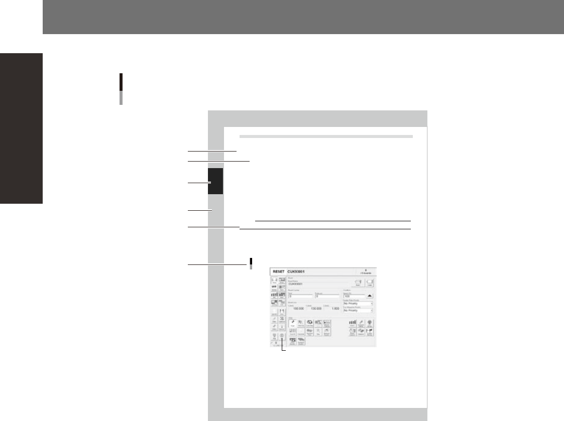
Typical page layout
Step
Chapter number
Chapter title
Substep or
description of step
Figure, picture
or table caption
Note, Caution
or Warning
23001-L0-00
n
Step
This describes the procedure for each operation.
n
Substep or description of step
This provides detailed information on the steps in the procedure.
n
Figure or table caption
This is the title of the figure or table and appears at the upper left.
n
Note, Caution or Warning
These are explained in detail in "Safety instructions".

Chapter 1 Part names and functions
Contents
1
3
2.1 Keyboard and mouse 1-3
4
3. Head assembly 1-5
3.1 Component pick-and-place head 1-6
3.1.1 10-in-line multi-head assembly 1-6
3.1.2 Multi-vision camera 1-6
3.2 Nozzle types 1-7
3.2.1 Nozzles for the 10-in-line head assemblies 1-7
9
4. Component supply section 1-13
4.1 Supplying components from feeder plates 1-13
4.1.1 Fixed feeder plates 1-13
4.1.2 Feeder exchange carriage 1-16
4.2 Supplying components from tray changer (sATS
II
7
5.
Conveyor unit 1-19
5.1
Conveyor unit 1-19
5.2 Sensor layout of conveyor unit 1-20
6. Axis configuration 1-22
5
7.1 Performing a nozzle shaft blow 1-26
1
8.1 Tape cutting during component mounting 1-31
8.2 Tape cutting during board conveying 1-32
2
3
9.1 Coplanarity checker 1-33
4
9.3 Recovery pallet 1-35
1-1
1
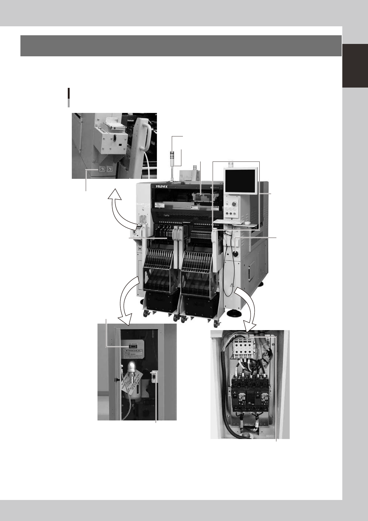
Part names and functions
1. Machine main unit
A standard machine has the following configurations after installation is complete. Names and functions of
major parts of the main unit are illustrated below.
Machine main unit
Alarm buzzer
Safety cover
Feeder setup section
Operation panel and
data input unit
Power switch
Power connection terminals
Air pressure supply/
shutoff switch
USB port
Signal light
Temporary tape set station
Pressure gauge
Left: A table
Right: B table
23100-L4-00