YS24X_Ope_E.pdf - 第42页
1-5 1 Part names and functions 3. Head assembly The head assemblies are mounted on two XY axes located on the A and B tables of the machine and move to pick up and place components. Head assembly Fiducial camera lighting…
1-4
1
Part names and functions
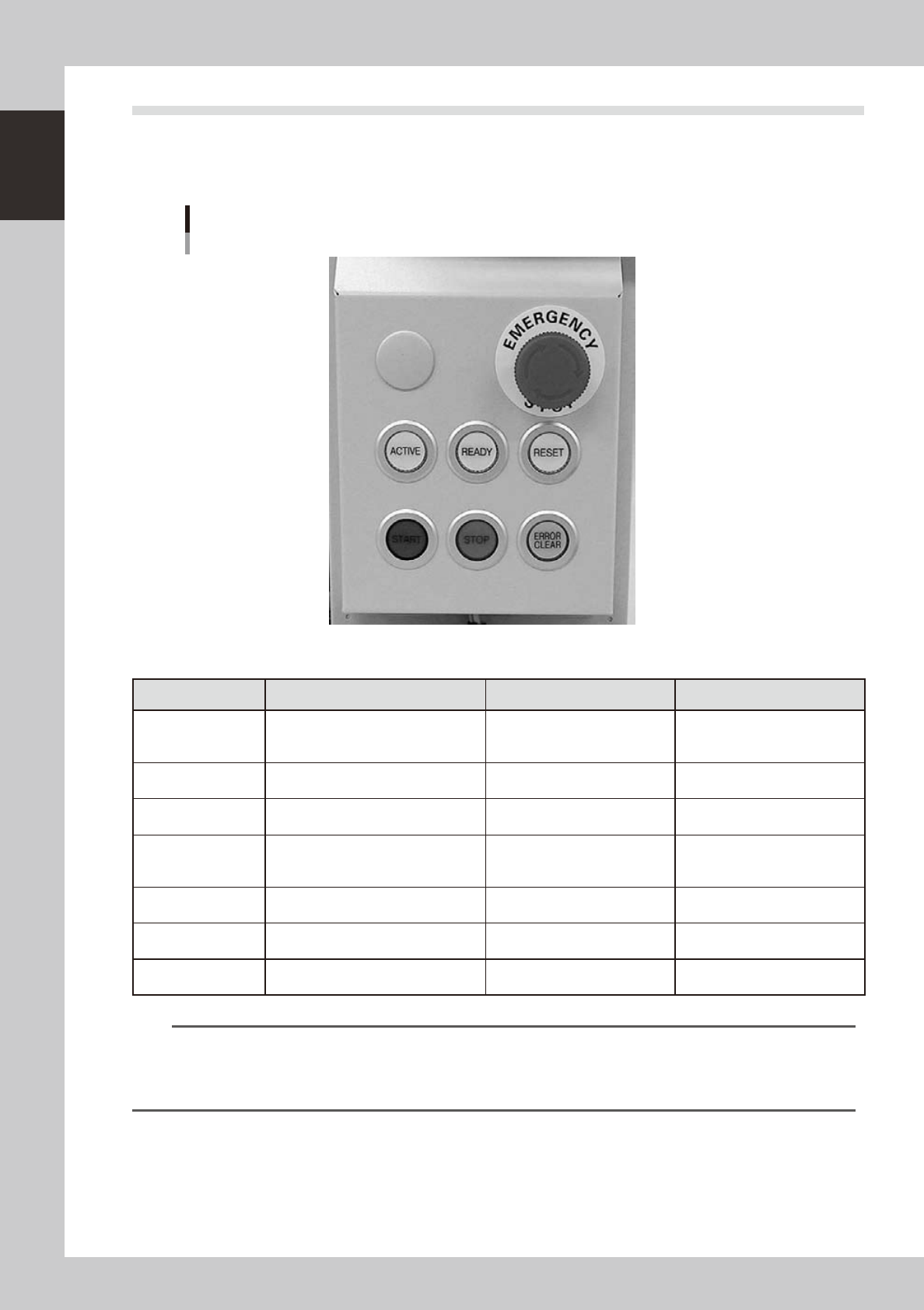
2.2 Operation panel buttons
The operation panel buttons are provided on the front and rear of the machine to run major commands
frequently used to operate the machine. Each button is lit while turned on. (The operation panel buttons light
up in the same colors specified by the signal light.)
Operation panel buttons
23103-L4-00
n
Operation panel button functions
Button name Use the button to: OFF ON
ACTIVE
Enable other keys. (The front and rear
[ACTIVE] keys cannot be turned on
simultaneously.)
• After machine has started.
• The other table has access
rights to operate machine.
• Has access rights to
operate machine.
READY
Release emergency stop and turn the
servo on.
• SERVO OFF
(Motor power OFF)
• SERVO ON
(Motor power ON)
RESET
Stop automatic operation and return to
standby for board production.
• Machine is in normal operation
or stopped.
• Machine has been reset.
START (green)
Perform component placement
according to board data.
• Machine is stopped.
• Machine is in normal operation.
[Flash]
Pause or step operation
STOP (Red/White)
Interrupt automatic operation. (Press
START to resume operation.)
• Machine is in normal operation. • Error occurred.
ERROR CLEAR
(Yellow/Blue)
Stop buzzer sound and clear error
screen.
• Machine is in normal operation. • Error occurred.
EMERGENCY STOP
Trigger emergency stop. Turn to the
right to release it.
n
NOTE
The [ACTIVE] button is provided on both front and rear (option) panels, but cannot be turned on simultaneously. This
means that the [READY], [START], [ERROR CLEAR] and [RESET] buttons are enabled only when the [ACTIVE] key on the
same panel is turned on. (The [STOP] button can be used when the [ACTIVE] button is either on or off.)
The keyboard is enabled only when the [ACTIVE] key on the front panel is on.
1-5
1
Part names and functions
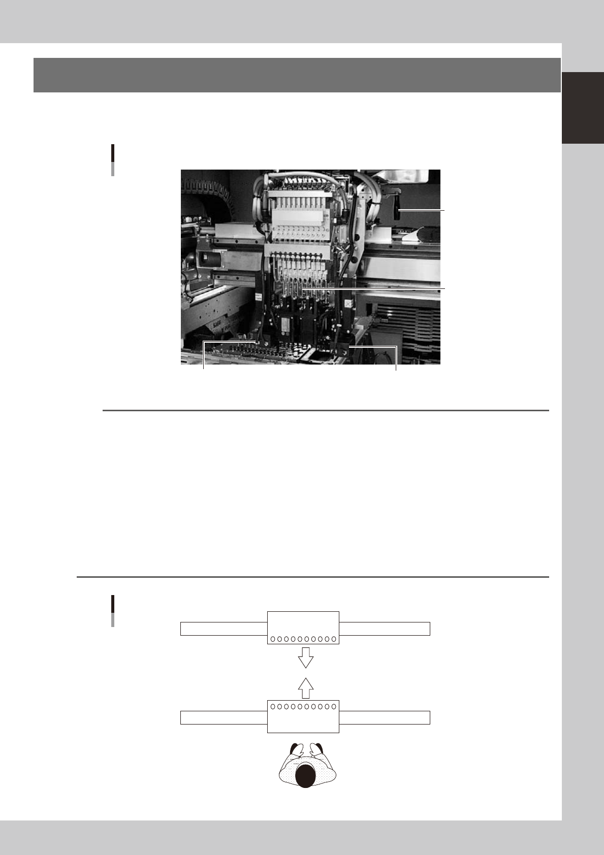
3. Head assembly
The head assemblies are mounted on two XY axes located on the A and B tables of the machine and move to
pick up and place components.
Head assembly
Fiducial camera lighting unit Fiducial camera lighting unit
10-in-line multi-head
Handle for moving
head assembly
(rear side)
23104-L4-00
n
NOTE
The mounting position of the fiducial camera lighting unit may vary depending on the specifications. (Note that the
double-fiducial camera specifications are optional.)
n
Dual - stage
• Right-to-left ow: The lighting unit is mounted on the head No. 10 side of the A-table head and B-table head (see
the figure below) when the machine has the single fiducial camera specifications.
• Left-to-right ow: The lighting unit is mounted on the head No. 1 side of the A-table head and B-table head (see
the figure below) when the machine has the single fiducial camera specifications.
n
Single-lane / Dual-lane
• Right-to-left ow: The lighting unit is mounted on the head No. 1 side of the A-table head and on the head
No. 10 side of the B-table head (see the figure below) when the machine has the single
fiducial camera specifications.
• Left-to-right ow: The lighting unit is mounted on the head No. 10 side of the A-table head and on the head
No. 1 side of the B-table head (see the figure below) when the machine has the single
fiducial camera specifications.
A
B
Head layout
10
10
1
1
Front of machine
23105-L4-00
1-6
1
Part names and functions
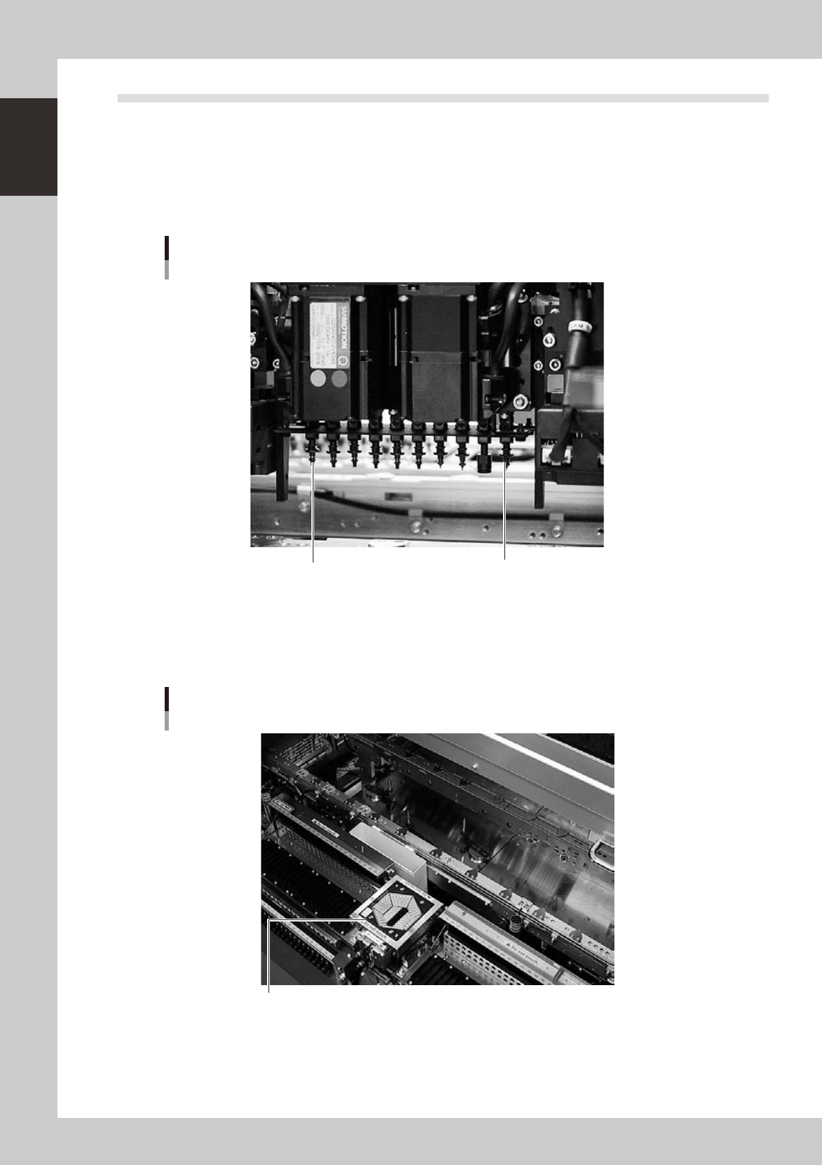
3.1 Component pick-and-place head
3.1.1 10-in-line multi-head assembly
The 10-in-line multi-head assembly has 10 heads arranged in a row to pick up and place components. Head
numbers are designated from 1 to 10, from the right as the B table is viewed from the front of the machine and
from the left as the A table is viewed from the front of the machine. The spacing of adjacent nozzles attached
to the head assembly is 12mm, which is identical to the pitch of the SS feeder bank.
Head 10
Head 1
10-in-line multi-head assembly
Example as the B table is viewed from the front of the machine.
23106-L4-00
3.1.2 Multi-vision camera
The YS24X is equipped with two component recognition cameras as standard which have a vertically movable
side-emitting light source and are installed on the front and rear sides of the machine.
Multi-vision camera
Multi-vision camera with vertically movable side-emitting light source
23120-L4-00