YS24X_Ope_E.pdf - 第43页
1-6 1 Part names and functions 3.1 Component pick-and-place head 3.1.1 10-in-line multi-head assembly T he 10-in-line multi-head assembly has 10 heads arranged in a row to pick up and place components. Head numbers are d…
1-5
1
Part names and functions
3. Head assembly
The head assemblies are mounted on two XY axes located on the A and B tables of the machine and move to
pick up and place components.
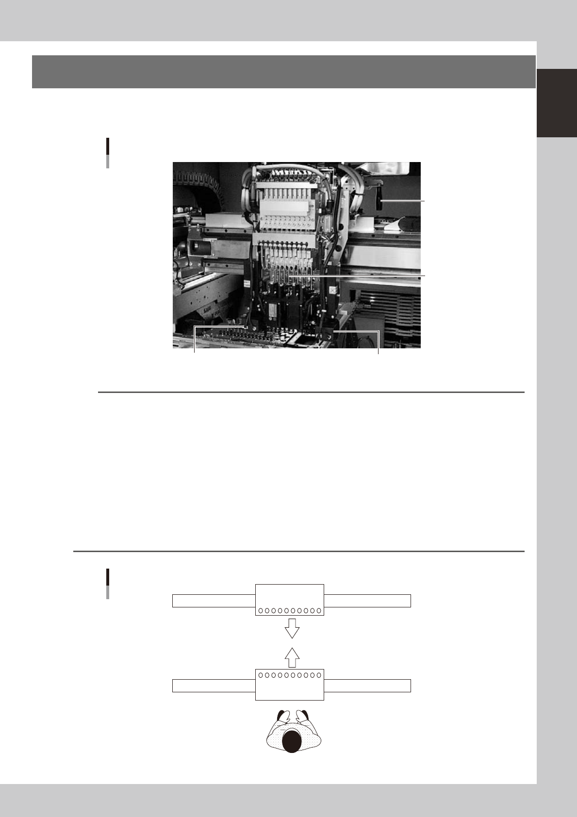
Head assembly
Fiducial camera lighting unit Fiducial camera lighting unit
10-in-line multi-head
Handle for moving
head assembly
(rear side)
23104-L4-00
n
NOTE
The mounting position of the fiducial camera lighting unit may vary depending on the specifications. (Note that the
double-fiducial camera specifications are optional.)
n
Dual - stage
• Right-to-left ow: The lighting unit is mounted on the head No. 10 side of the A-table head and B-table head (see
the figure below) when the machine has the single fiducial camera specifications.
• Left-to-right ow: The lighting unit is mounted on the head No. 1 side of the A-table head and B-table head (see
the figure below) when the machine has the single fiducial camera specifications.
n
Single-lane / Dual-lane
• Right-to-left ow: The lighting unit is mounted on the head No. 1 side of the A-table head and on the head
No. 10 side of the B-table head (see the figure below) when the machine has the single
fiducial camera specifications.
• Left-to-right ow: The lighting unit is mounted on the head No. 10 side of the A-table head and on the head
No. 1 side of the B-table head (see the figure below) when the machine has the single
fiducial camera specifications.
A
B
Head layout
10
10
1
1
Front of machine
23105-L4-00
1-6
1
Part names and functions
3.1 Component pick-and-place head
3.1.1 10-in-line multi-head assembly
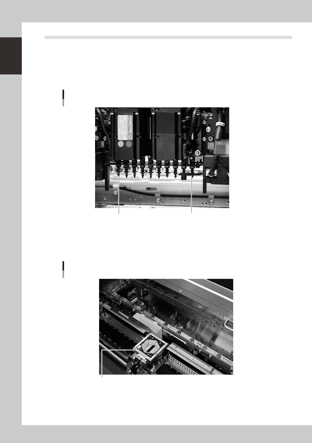
The 10-in-line multi-head assembly has 10 heads arranged in a row to pick up and place components. Head
numbers are designated from 1 to 10, from the right as the B table is viewed from the front of the machine and
from the left as the A table is viewed from the front of the machine. The spacing of adjacent nozzles attached
to the head assembly is 12mm, which is identical to the pitch of the SS feeder bank.
Head 10
Head 1
10-in-line multi-head assembly
Example as the B table is viewed from the front of the machine.
23106-L4-00
3.1.2 Multi-vision camera
The YS24X is equipped with two component recognition cameras as standard which have a vertically movable
side-emitting light source and are installed on the front and rear sides of the machine.
Multi-vision camera
Multi-vision camera with vertically movable side-emitting light source
23120-L4-00
1-7
1
Part names and functions
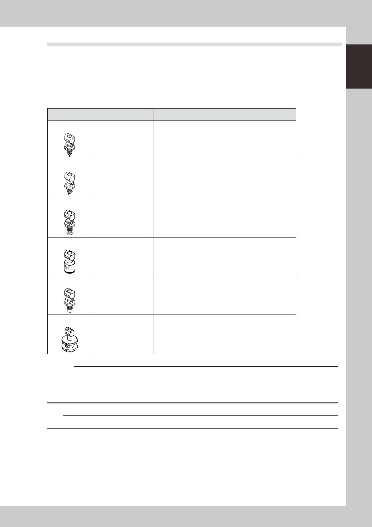
3.2 Nozzle types
To ensure stable component pickup, the correct nozzle that matches the component must be used. The
following sections explain typical nozzles which can be attached to each head.
3.2.1 Nozzles for the 10-in-line head assemblies
n
Standard type
Six types of standard nozzles can be chosen and attached to each head.
Nozzle type Head No. Typical Components
Type 301A
1 to 10 0603 to 1005 size components
Type 302A
1 to 10 1608 to 3216 size components
Type 303A
1 to 10 4532 to 7343 size components and SOP
Type 304A
1 to 10 QFP, etc.
Type 306A
1 to 10 Cylindrical chip (Melf type) components only
Type 307A
3, 8 32x32mm to 45x45mm size components
c
other machines.
Type 307A nozzle can only be attached to heads 3 and 8 with a custom nozzle holder. The maximum nozzle diameter
n
NOTE
For detailed information on component types and size, refer to the specification sheets that come with the machine.