YS24X_Ope_E.pdf - 第52页
1-15 1 Part names and functions n Single-lane / Dual-lane Feeder plate layout Single-lane / Dual-lane 1 24 25 48 148 125 124 101 A B 10 1 1 10 (12mm pitch) 1 24 25 48 11 4 101 A B 10 1 1 10 1 24 25 48 160 101 B B 10 1 A …
1-14
1
Part names and functions
Head No. and feeder set No.
Some feeders cannot be reached by a head depending on the head assembly configuration and X-axis movement range.
The tables below show feeder set numbers that can be accessed by each head of the machine.
n
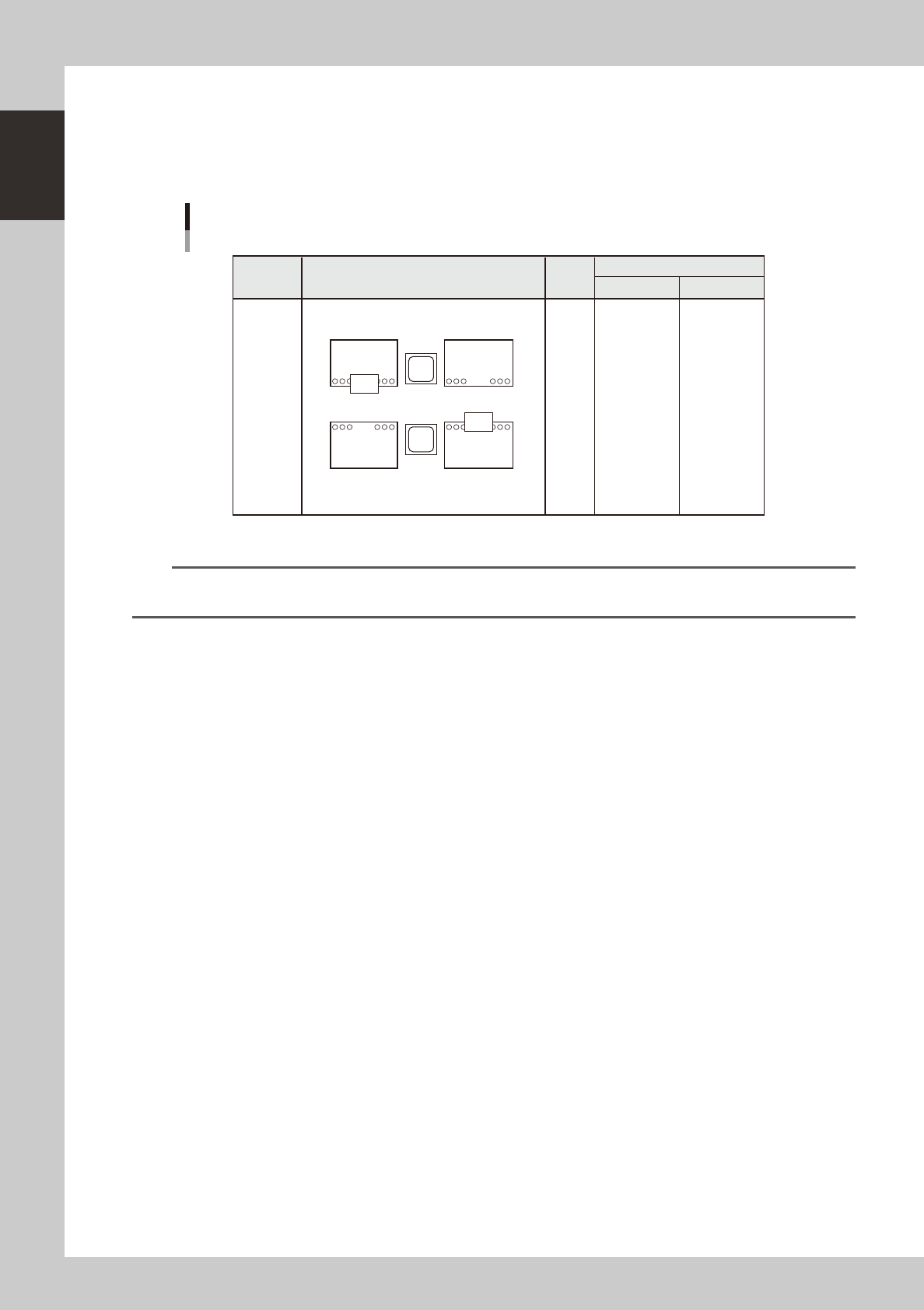
Dual - stage
Feeder plate layout
Dual - stage
Feeder set No.
Layout
Head
No.
Type
A table B table
1
2
3
4
5
6
7
8
9
10
1 to 39
2 to 40
3 to 41
4 to 42
5 to 43
6 to 44
7 to 45
8 to 46
9 to 47
10 to 48
101 to 139
102 to 140
103 to 141
104 to 142
105 to 143
106 to 144
107 to 145
108 to 146
109 to 147
110 to 148
1
24
25
48
148
125
124
101
A
B
10 1
1 10
Fixed
24-feeder
plate or
24-feeder
exchange
carriage
23110-L4-00
n
NOTE
Accessible feeder positions may differ from the above when the Feeder Definition parameter in component
information is set to "Teach" or "Relative".
1-15
1
Part names and functions
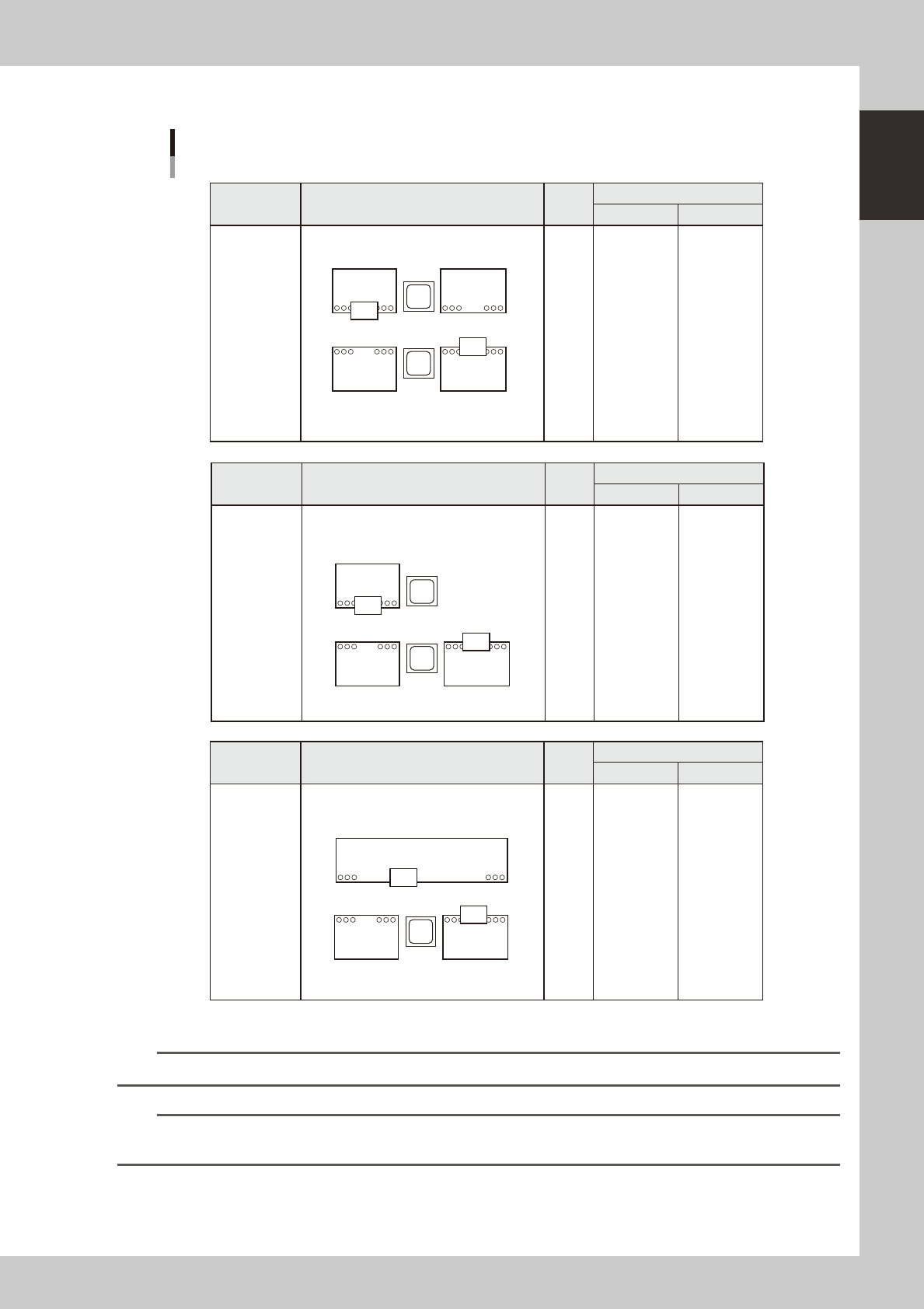
n
Single-lane / Dual-lane
Feeder plate layout
Single-lane / Dual-lane
1
24
25
48
148
125
124
101
A
B
10 1
1 10
(12mm pitch)
1
24
25
48
114
101
A
B
10 1
1 10
1
24
25
48
160
101
B
B
10 1
A
1 10
1
2
3
4
5
6
7
8
9
10
1
2
3
4
5
6
7
8
9
10
101 to 105
101 to 106
101 to 107
101 to 108
101 to 109
101 to 110
101 to 111
101 to 112
101 to 113
101 to 114
101 to 151
102 to 152
103 to 153
104 to 154
105 to 155
106 to 156
107 to 157
108 to 158
109 to 159
110 to 160
sATSII
specifications
(Fixed
14-feeder plate
on rear side)
24-feeder plate
on front side
60-feeder plate
on rear side
Feeder set No.
Layout
Head
No.
Type
A table B table
Feeder set No.
Layout
Head
No.
Type
A table B table
Feeder set No.
Layout
Head
No.
Type
A table B table
1
2
3
4
5
6
7
8
9
10
1 to 39
2 to 40
3 to 41
4 to 42
5 to 43
6 to 44
7 to 45
8 to 46
9 to 47
10 to 48
1 to 39
2 to 40
3 to 41
4 to 42
5 to 43
6 to 44
7 to 45
8 to 46
9 to 47
10 to 48
1 to 39
2 to 40
3 to 41
4 to 42
5 to 43
6 to 44
7 to 45
8 to 46
9 to 47
10 to 48
101 to 139
102 to 140
103 to 141
104 to 142
105 to 143
106 to 144
107 to 145
108 to 146
109 to 147
110 to 148
Fixed
24-feeder plate
or 24-feeder
exchange
carriage
23119-L4-10
n
NOTE
Rear feeder plate of sATS
II
type is a fixed plate with 12mm pitch feeder installation holes.
n
NOTE
Accessible feeder positions may differ from the above when the Feeder Definition parameter in component
information is set to "Teach" or "Relative".
1-16
1
Part names and functions
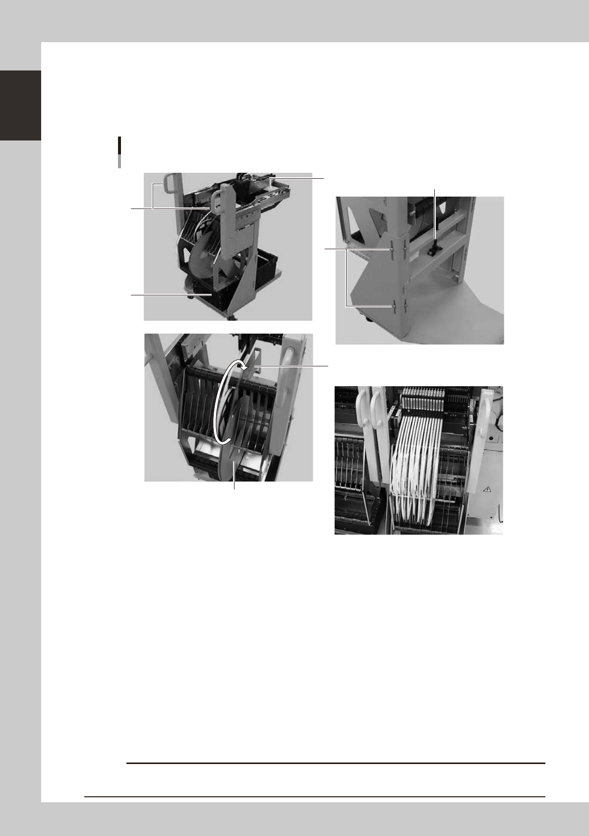
4.1.2 Feeder exchange carriage
The feeder exchange carriage allows feeder setup in advance for the next production boards. The feeders on
the feeder exchange carriage can be changed at one time.
n
Feeder exchange carriage
External view of feeder exchange carriage
1
2
4
6
5
3
Placing 7-inch reels continuously
A tape reel larger than 7 inches
23111-L4-00
1. Handle
Use this handle to move and position the feeder exchange carriage.
2. Feeder plate
Up to 24 SS feeders (8mm) can be installed on this feeder plate.
3. Vertical clamp bolts
If necessary to adjust the feeder plate height, loosen these bolts and change their clamping positions. (8 places)
4. Empty tape dump box (option)
This box is for catching empty tape after components have been picked up.
5. Height adjustment bolt
After loosening the vertical clamp bolts, turn this bolt to adjust the feeder plate height.
6. Reel holder
Each reel holder holds one tape reel (7 inches) for 8mm tape feeders.
When using a tape reel larger than 7 inches, raise this reel holder as shown above.
c
above.