YS24X_Ope_E.pdf - 第54页
1-17 1 Part names and functions 4.2 Supplying components from tray changer (sA TS II ) T ra y changer (sA TS II ) part names and functions are described below . n NOTE The sA TS II can only be installed in single - lane …
1-16
1
Part names and functions
4.1.2 Feeder exchange carriage
The feeder exchange carriage allows feeder setup in advance for the next production boards. The feeders on
the feeder exchange carriage can be changed at one time.
n
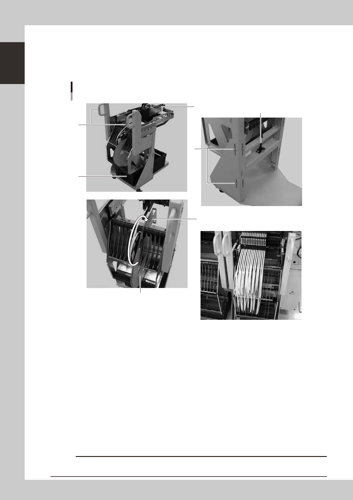
Feeder exchange carriage
External view of feeder exchange carriage
1
2
4
6
5
3
Placing 7-inch reels continuously
A tape reel larger than 7 inches
23111-L4-00
1. Handle
Use this handle to move and position the feeder exchange carriage.
2. Feeder plate
Up to 24 SS feeders (8mm) can be installed on this feeder plate.
3. Vertical clamp bolts
If necessary to adjust the feeder plate height, loosen these bolts and change their clamping positions. (8 places)
4. Empty tape dump box (option)
This box is for catching empty tape after components have been picked up.
5. Height adjustment bolt
After loosening the vertical clamp bolts, turn this bolt to adjust the feeder plate height.
6. Reel holder
Each reel holder holds one tape reel (7 inches) for 8mm tape feeders.
When using a tape reel larger than 7 inches, raise this reel holder as shown above.
c
above.
1-17
1
Part names and functions
4.2 Supplying components from tray changer (sATS
II
)
Tray changer (sATS
II
) part names and functions are described below.
n
NOTE
The sATS
II
can only be installed in single - lane machines.
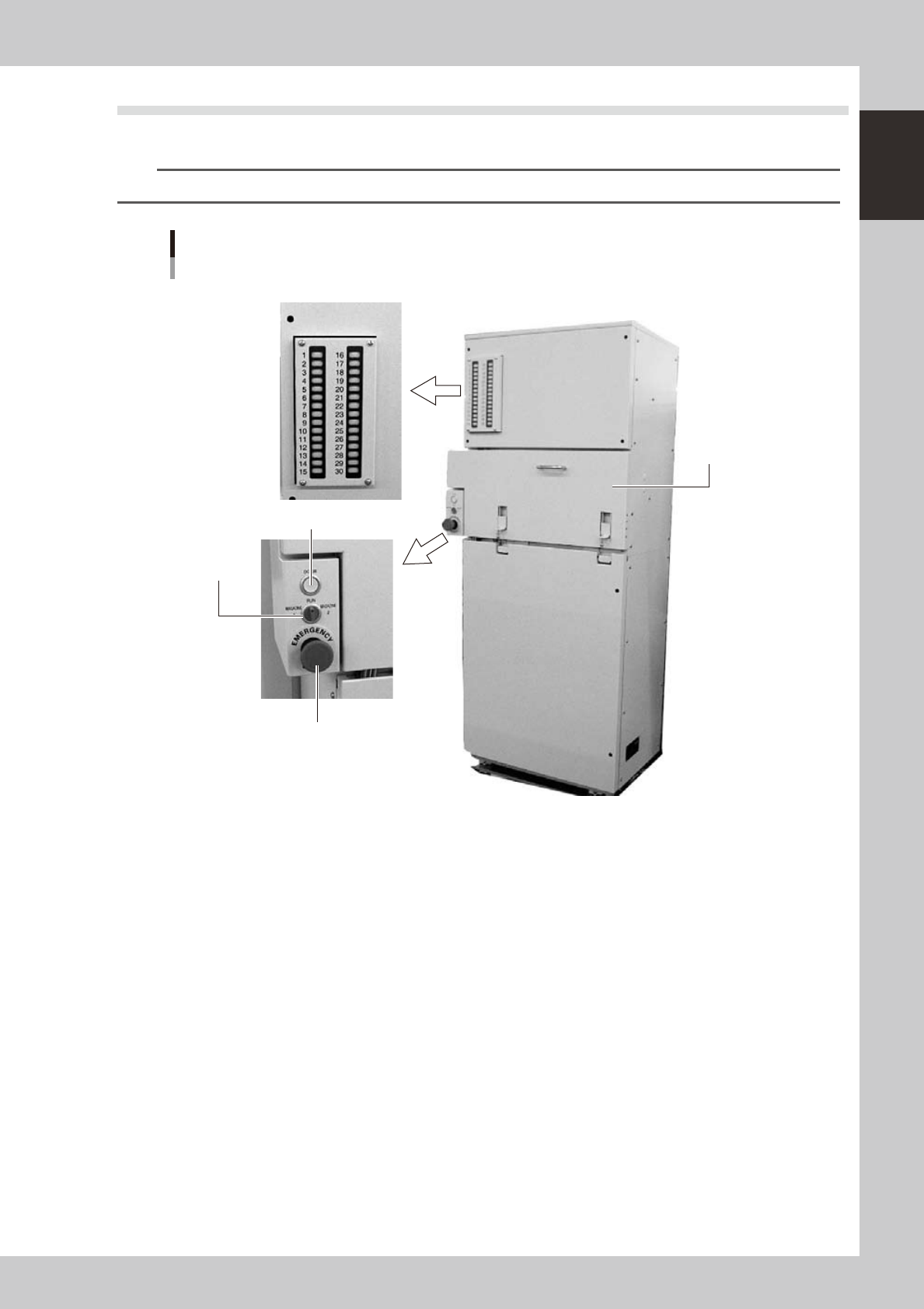
sATSII main unit
Pallet insertion side
1. Magazine door
2. Emergency stop button
3. DOOR switch
4. DOOR indicator lamp
5. Pallet indicator lamp
23112-L4-00
1. Magazine door
Open this door when exchanging a pallet or a magazine. Two magazines (Magazine 1, Magazine 2) can be
accommodated vertically.
2. Emergency stop button
Pressing this button triggers emergency stop, the same as the emergency stop buttons on the mounter.
3. DOOR switch
Placing this switch in "MAGAZINE 1" or "MAGAZINE 2" unlocks the magazine door, so you can open it. When this switch
is in the RUN position, the door is locked and you cannot open it.
Place this switch in "MAGAZINE 1" when exchanging Magazine 1, and in "MAGAZINE 2" when exchanging Magazine 2.
4. DOOR indicator lamp
This indicator lamp lights up when the magazine door is locked and turns off when unlocked.
1-18
1
Part names and functions
5. Pallet indicator lamp
The indicator lamp for the pallet No. set in the parts information is lit up. When the tray components on a pallet are used
up, the indicator lamp for that pallet No. flashes (see below). Pallet indicator lamps No. 1 to No. 15 are for Magazine 1.
Pallet indicator lamps No. 16 to No. 30 are for Magazine 2.
After you set new pallets in the magazines, press the flashing indicator buttons to reset them.
n
Relation between pallet indicator numbers and magazines
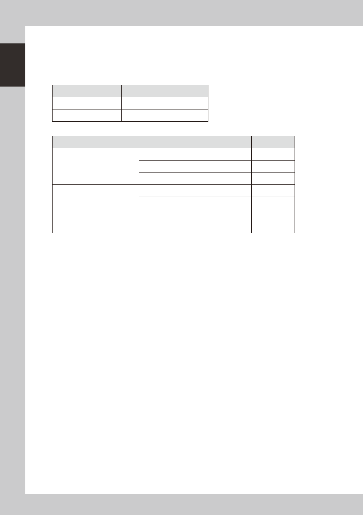
Pallet indicator number Magazine
1 to 15 Magazine 1 for stage 1
16 to 30 Magazine 2 for stage 1
n
Pallet indicator lighting pattern
Pallet condition Component condition Indicator status
One component type on one pallet
Components have been supplied. ON
Used up all components. Flashing
Components are currently being used. ON
Two or more components types on one
pallet
All components on pallet have been supplied. ON
Used up all components. Flashing
Used up at least one type of component. Flashing
Components to be used are not specified in board data. OFF