YS24X_Ope_E.pdf - 第57页
1-20 1 Part names and functions 5.2 Sensor layout of conveyor unit T he following shows the sensor la yout of the conv eyor unit. n Dual-stage Sensor layout Entrance sensor N 01008C 3 Exit sensor N 01008D6 Standby positi…
1-19
1
Part names and functions
5.
Conveyor unit
5.1
Conveyor unit
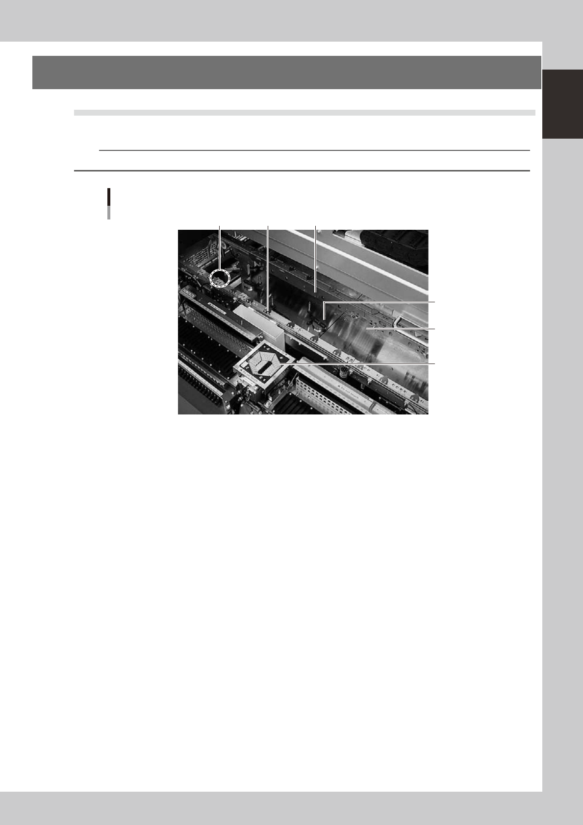
The conveyor unit used to clamp a board in mounting position is described below.
n
NOTE
In dual-lane machines, the front side is "Lane 1" and the rear side is "Lane 2".
4 5
2
3
1
6
Conveyor unit
Example of Single-lane
23113-L4-00
1. Main stopper
When a board is carried in on the conveyor, the main stopper halts travel of the board in the component mounting
position.
In the case of dual-stage machines, the main stopper is installed at one location of stage 1 and two locations of stage 2.
The main stopper on stage 2 is changed to an appropriate one according to the board size.
2. Push-up plate
The push-up plate clamps the board up against the conveyor rails, with the supporter pins attached by magnet on the
push-up plate.
3. Push-up pins
These pins are arranged on the push-up plate and secure the board by pushing it up from the bottom.
4. Board hold plate (movable)
These plates hold the edges of the board from above when the board is clamped in the mounting position.
5. Board edge clamp unit
This unit clamps the board by pushing its edges up against the board hold plates.
6. Multi-vision camera (with vertically movable side-emitting light source)
One camera each is installed on the front and rear of the machine to perform component recognition.
1-20
1
Part names and functions
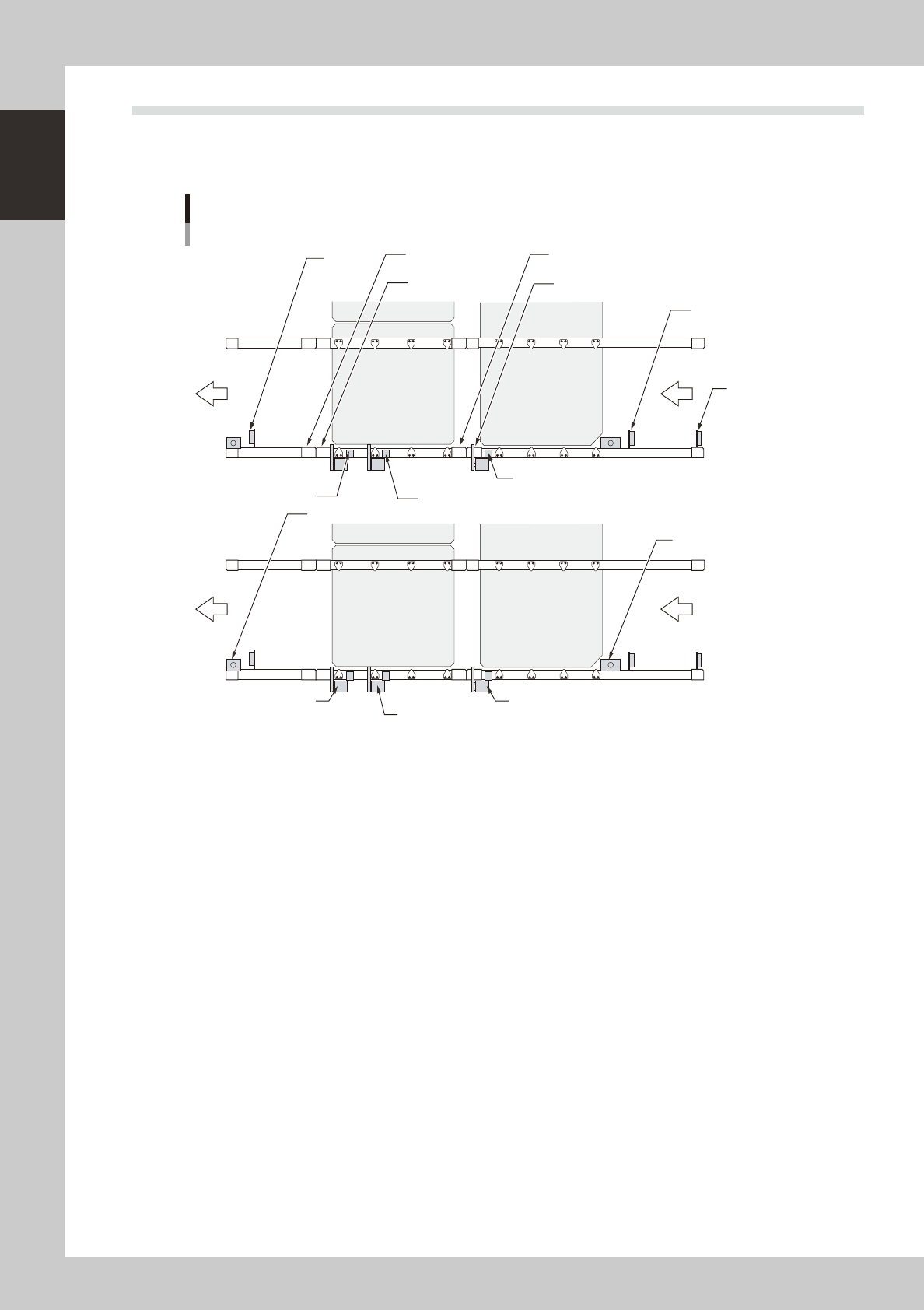
5.2 Sensor layout of conveyor unit
The following shows the sensor layout of the conveyor unit.
n
Dual-stage
Sensor layout
Entrance sensor
N 01008C 3
Exit sensor
N 01008D6
Standby position sensor
N 01008C 0
Hazard (personal injury)
sensor N 01008D 5
Hazard (personal injury)
sensor N 01008D 3
Hazard (personal injury) sensor
N 01008D 2
Hazard (personal injury) sensor
N 01008E 5
Board sensor 1 of component
mounting 2 N 01008D 0
Board sensor 2 of component mounting 2
N 01008D 1
Board sensor of component mounting 1
N 0100903
Exit stopper
Standby position stopper
N 01008F6
Stopper 1 of component
N 01008F0
Stopper 2 of component
mounting 2 N 0100944
Stopper of component
mounting 1 N 0100943
Component
mounting stage 1
Component
mounting stage 1
Component
mounting stage 1
Component
mounting stage 1
23114-L4-00
1-21
1
Part names and functions
n
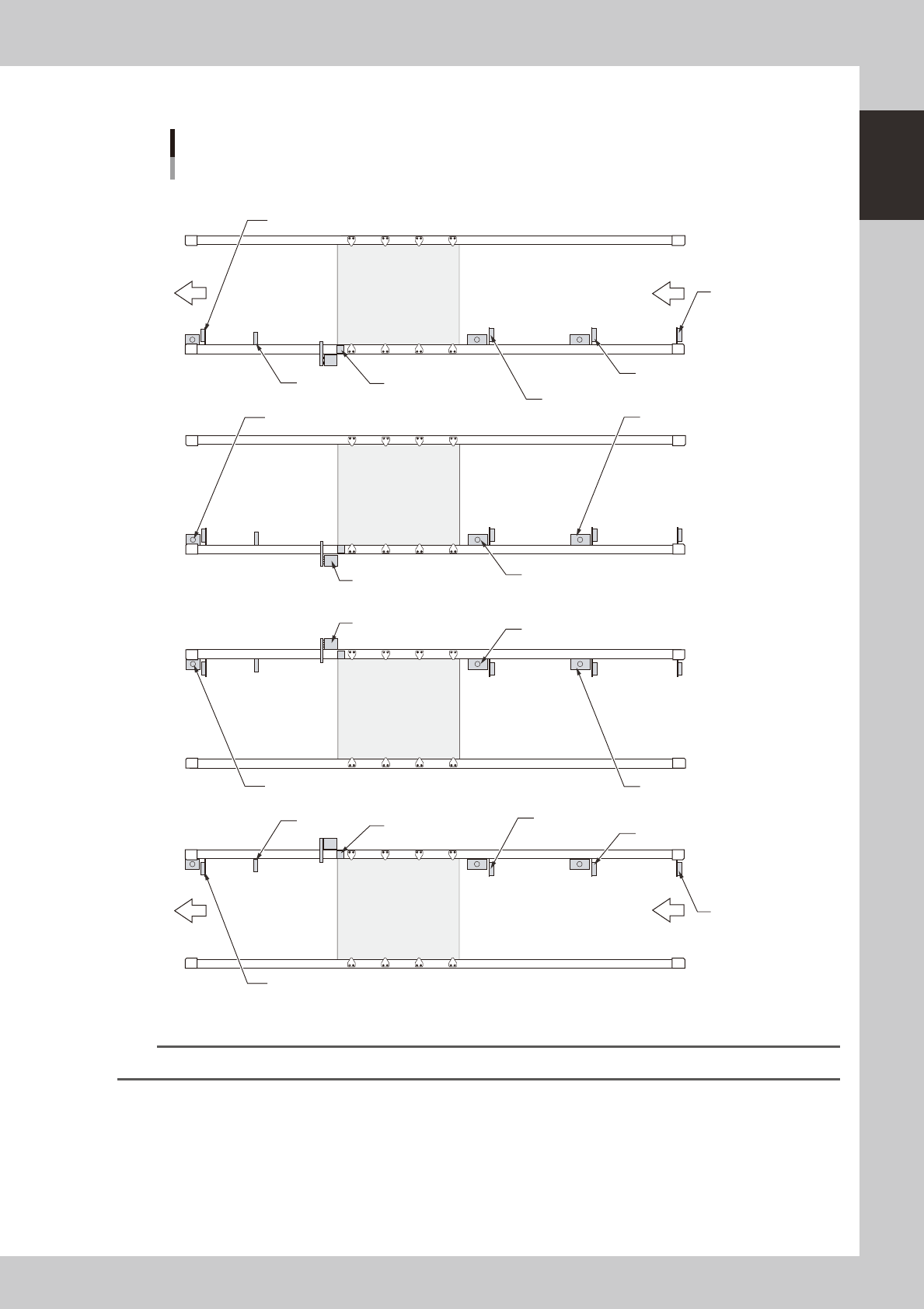
Single-lane/Dual-lane
Sensor layout
N Lane 1
N Lane 2
Entrance sensor
N 01008C 5
Exit sensor
N 01008D3
Standby position sensor 1
N 01008C 0
Standby position sensor 2
N 01008C 7
Board sensor 1 of component
mounting N 01008C1
WorkOut
N0100903
Exit stopper
with no sensor
Standby position stopper 1
N 01008C3
Standby position stopper 2
N 01008E4
Stopper of component 1
N 01008D5
Entrance sensor
N01008C6
Exit sensor
N01008D4
Standby position sensor 1
N01008D0
Standby position sensor 2
N01008E1
Board sensor 1 of component
mounting N01008D1
WorkOut
N0100917
Exit stopper
with no sensor
Standby position stopper 1
N01008C4
Standby position stopper 2
N01008E5
Stopper of component 1
N01008D7
23115-L4-10
n
NOTE
Only Lane 1 applies to single-lane machines.